571D-C Cable Assembly Instructions
Printable PDF: 571D-C Cable Assembly Instructions
(TriSoncia-Cable-Assembly-Instructions-20464.pdf)
Download this content as a pdf.
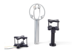
The 571D-C cable kit is to create a homemade cable to connect the LI-550P TriSonica Mini or LI-560 TriSonica Sphere sonic anemometers to the LI-570 Data Logger. This document describes how to create the cable using the parts supplied with the kit.
The kit includes two connector assemblies, consisting of an insulated contact assembly, locking collar, spring, seal bushing, strain relief, and shell. You provide a cable with 5 wire leads, 22 AWG (0.33 mm2) stranded wire, 6.2 to 7 mm diameter (required for ingress protection; smaller wires will not seal), 25 meters maximum length. You also need a soldering iron and solder. Allow about 30 minutes to an hour to assemble the cable if you are experienced with solder connections.
- Trim the cable to the desired length (maximum of 25 meters).
- Remove about 10 mm of insulation from the ends of the cable, and strip 2 mm of insulation off of each wire.

- Twist the strands of each wire just enough to prevent unraveling.
- Assemble the connector components and cable.
- Insert the cable through the shell, strain relief, bushing, spring, and locking collar in the order shown.

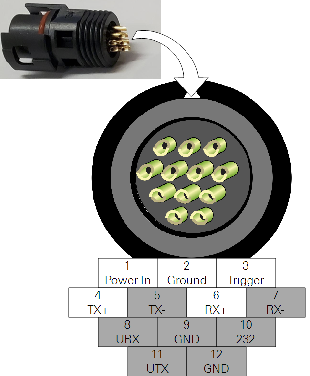
- Solder the wires to contacts.
- For each pin and wire, set the wire in the solder cup and secure it with a small amount of solder. Wire colors and assignments are arbitrary; you can use any wire for any purpose. The important thing is to wire pin 1 to 1, pin 2 to 2, pin 3 to 3, pin 4 to 4 and pin 6 to 6. The other pins are not used in this application.
- Assemble the connector.
- Align the components and slide them together. Tighten the shell snugly over the contact assembly.
- Follow the same steps with the other end of the cable.
- Optional: Check the connections with an ohm meter.
- There should be no resistance across connected pins and infinite resistance across the pins that are not connected.
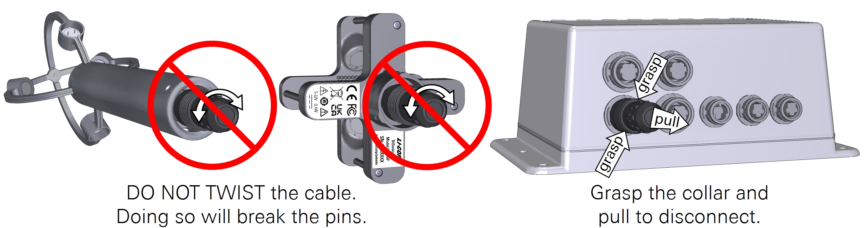
Important: Do not twist the cable during installation or removal. Doing so will damage the connector pins. To remove the cable, grasp the collar and pull it away from the anemometer.