Assembling the system
Initial assembly
The basic assembly instructions are given here.
Installing the system power supply cable
Connect the main power supply conduit to the small opening in the enclosure. Orient the lock-nut teeth so that they make contact with the enclosure surface. Connect the main power supply wires to terminals 3, 4 and 5.
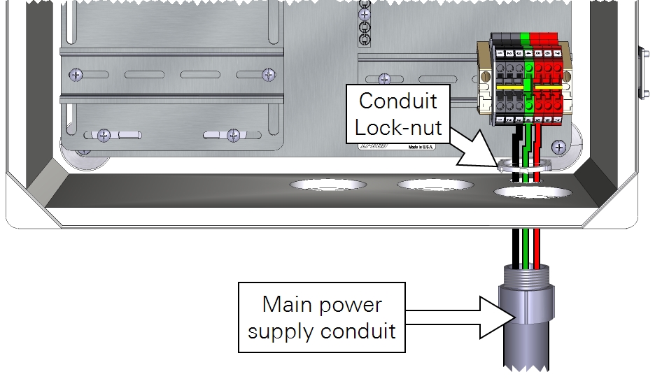
As a good practice, be sure that your power cable is not connected to a power source until the wiring is complete. Keep the breakers in the OFF position until you are ready to power up the system.
| From | Wire Color | To |
|---|---|---|
| Main power (-) | black | DIN Terminal 3 (bottom) |
| Earth ground | green | DIN Terminal 4 (bottom) |
| Main power (+) | red | DIN Terminal 5 (bottom) |
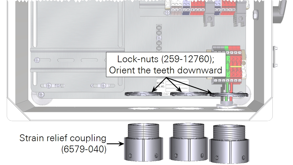
Installing strain relief couplings
Three strain relief couplings fit into the openings in the bottom of the enclosure. Orient the lock-nut teeth so that they make contact with the enclosure surface.
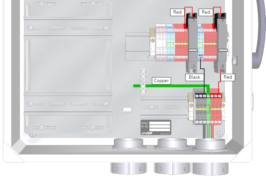
Installing system power supply wires
Install the wire leads from the accessories kit. These distribute power from the breakers to the DIN terminals.
| From | Wire Color | To |
|---|---|---|
| DIN Terminal 3 (top) | black | DIN Terminal 18 (bottom) |
| DIN Terminal 4 (top) | green/yelllow | Ground lug |
| DIN Terminal 7 (top) | red | Right breaker (bottom) |
| Left breaker (top) | red | DIN Terminal 16 (top) |
| Right breaker (top) | red | DIN Terminal 22 (top) |
Installing the backup battery
If you do not have the backup battery, skip this step. The backup battery, in combination with the DRM, will continue to power some components while powering off others by activating or deactivating switched power supplies if the main power supply goes down. The DRM charges the backup battery during normal operation.
The battery is to be installed under the DAqM plate, between the two risers. The cable has a connector with bare leads that connect to the DRM. Begin by connecting the bare leads to the DRM. To prevent the battery from becoming discharged, leave the connector disconnected until you are ready to deploy the system.
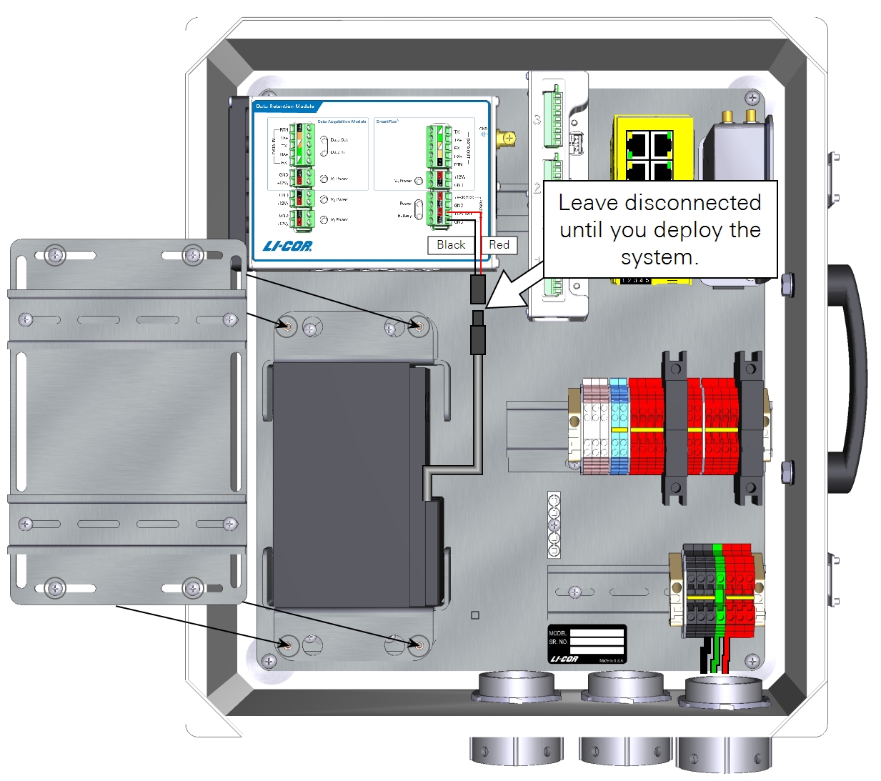
| From | Wire Color | To |
|---|---|---|
| Backup battery | black | DRM POWER IN GND |
| Backup battery | red | DRM POWER IN +12V BAT |
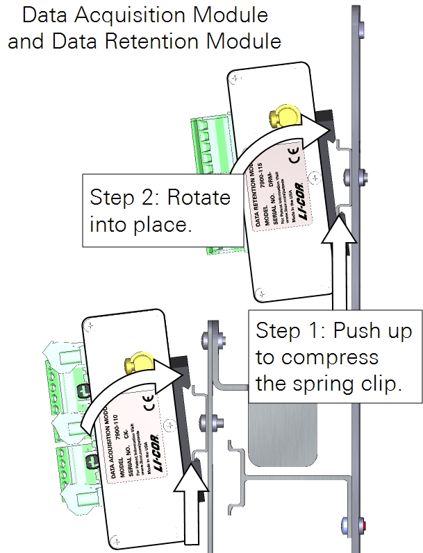
Installing the DRM and DAqM
The DAqMs and DRM should be mounted to the DIN rails on the left side of the enclosure. The SmartFlux System and network switch should be mounted to the upper DIN rail on the right side of the enclosure.
Preparing the SmartFlux System and network switch
Follow the steps below when installing the SmartFlux System in the 7900-050 Eddy Covariance System Enclosure or 7900-126 Biomet Data Acquisition System Enclosure. If you are using a different enclosure, connect the power and data cables similarly to what is described here.
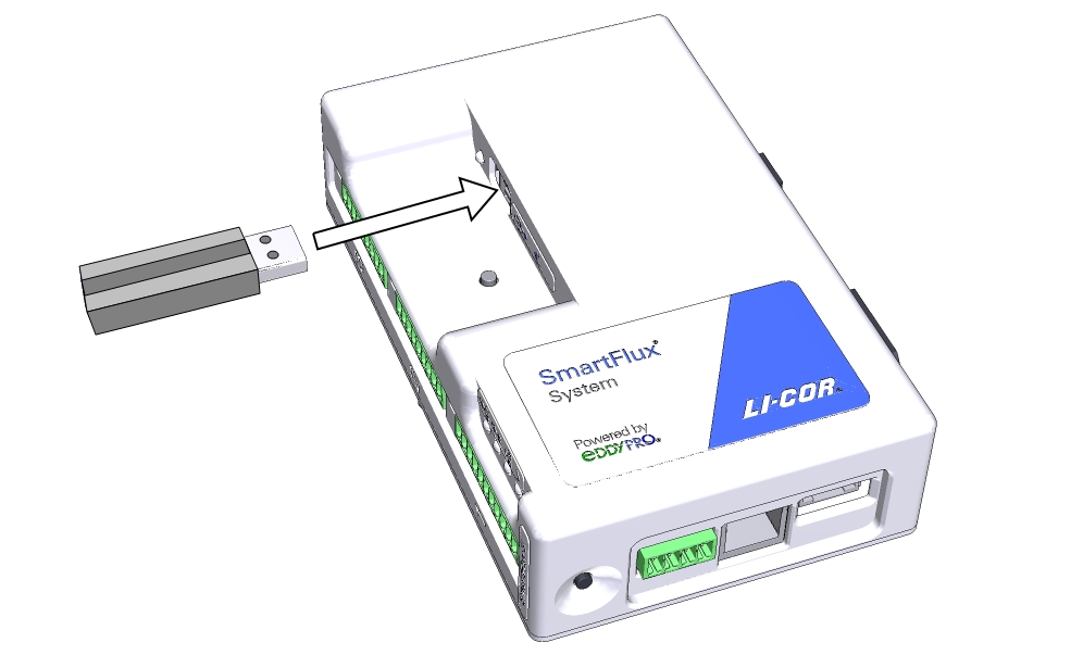
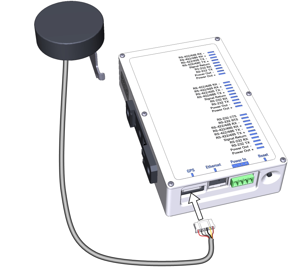
Install the USB drive
Data are recorded to the USB drive. Install the USB drive in the USB port on the SmartFlux System.
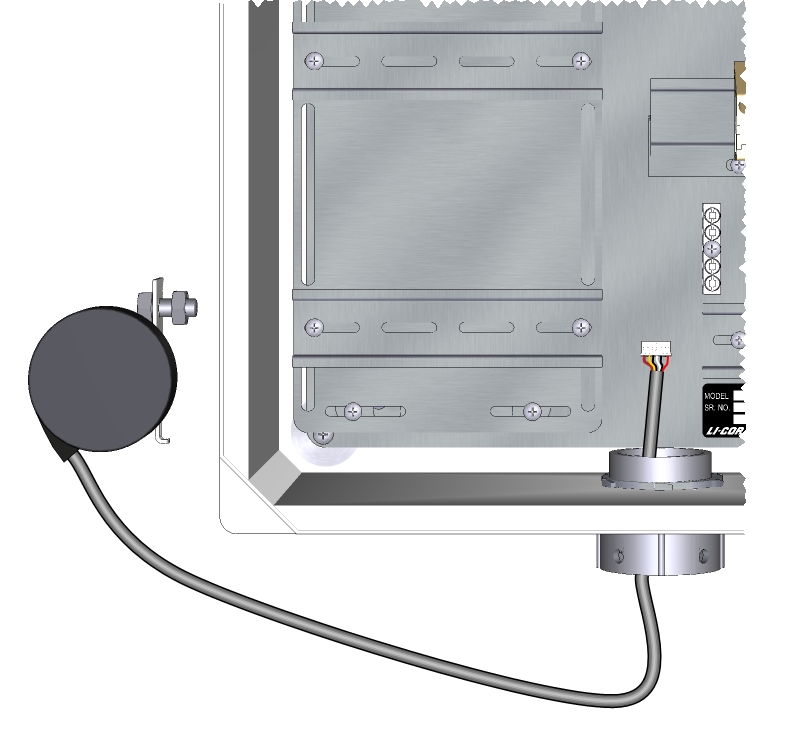
Connect the GPS antenna cable
Route the GPS cable through the left opening at the bottom of the enclosure and plug it into the GPS port on the SmartFlux System.
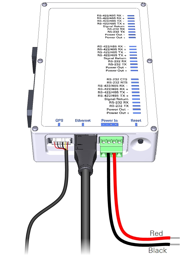
Connect power wires and the Ethernet cable to the SmartFlux System
Connect wire leads to the positive and negative terminals on the SmartFlux System. The black lead connects to negative (-), the red lead connects to positive (+). Plug in the 30 cm Ethernet cable that came with the SmartFlux System. There are two connections for positive (+) and two for negative (-). Use only one pair of +/- terminals.
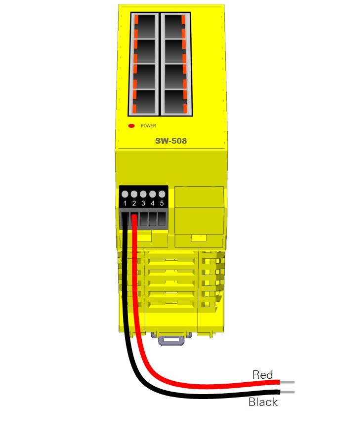
Connect power wires to the Brainboxes network switch
Power wires connect to the positive and negative terminals on the switch. The black lead connects to terminal 1 (-), the red lead connects to terminal 2 (+).
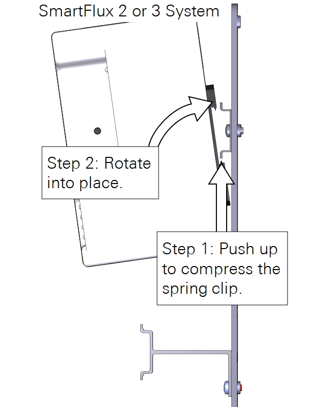
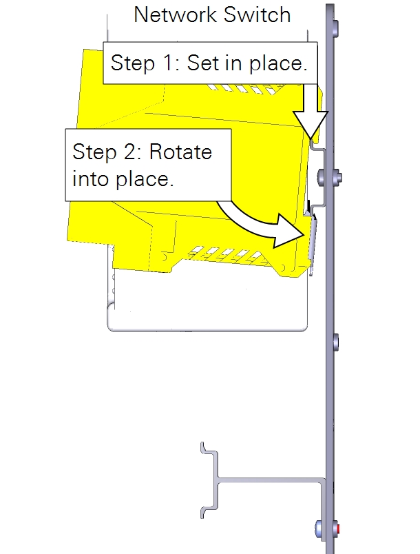
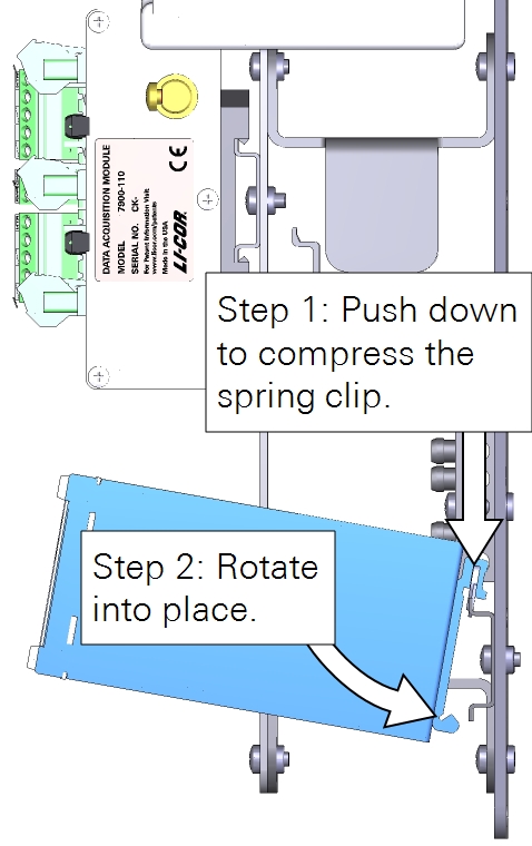
Installing the SmartFlux System and network switch
Install the SmartFlux 2 or 3 System onto left side of the upper-right DIN rail. Insert the spring-loaded clip on the bottom edge of the DIN rail and compress the spring. Rotate it into place. Mount the switch next to it.
Installing power and ground wires for components
With the 7900-126 enclosure, each component is powered individually from the power supply terminals, the DC-DC converter, or the DRM power outputs. 24-volt and 12-volt power supplies will be wired differently.
Caution: Do not short circuit the power supplies. For example, avoid connecting the V4 POWER OUT terminals from a Data Retention Module to the Power In terminals on a device that is powered from another power supply. Doing so will damage components and may present risk of a fire.
Select the power supply option that describes your system:
- 24 VDC power supply with Data Retention Module. This configuration uses the 24 volt output from a SunWize solar power supply. The DRM provides voltage regulation for devices that are not compatible with the 24 volt power supply.
- 12 VDC power supply with Data Retention Module. With a 12 volt power supply, no voltage regulator is needed.
- 12 VDC power supply with no Data Retention Module. With a 12 volt power supply, no voltage regulator is needed.
- 24 VDC power supply with the TDK-Lambda DC-DC converter. With a 24 volt power supply and no Data Retention Module, the TDK-Lambda voltage regulator should be used to power devices that have maximum power supply limits lower than 24 VDC.
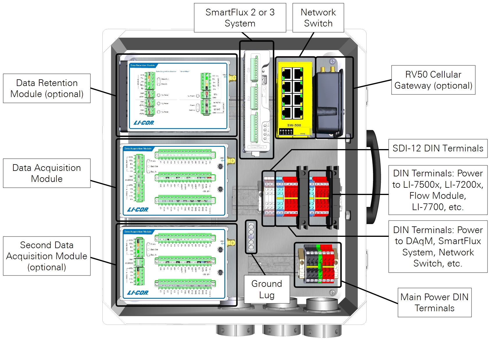
24 VDC power supply with Data Retention Module
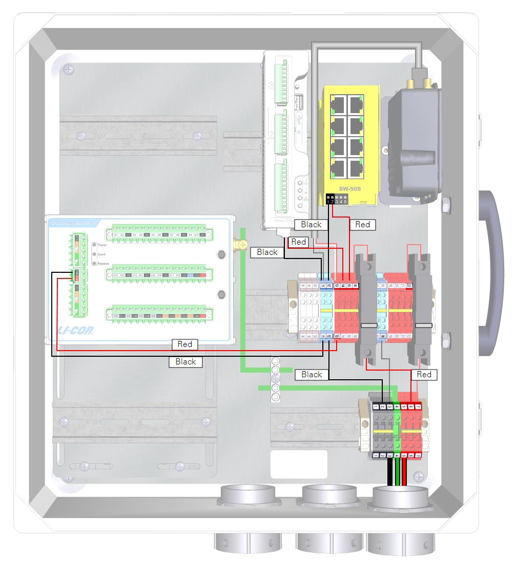
With a 24 VDC power supply, the DRM V3 power outputs can be used to power low-voltage components through the left 10-amp breaker and DIN terminals. Components powered in this manner include the network switch, PhenoCam, cellular gateway, satellite modem, CNF4 heater and ventilation unit (for the CNR4), or self-calibrating soil heat flux plates (HFP01SC).
| From | Wire Color | To |
|---|---|---|
| DRM and DAqM Ground Lugs | yellow/green | Enclosure Ground Lug |
| DIN Terminal 1 (top) | black | DRM POWER IN GND (-) |
| DIN Terminal 5 (top) | red | DRM POWER IN +9-30 VDC (+) |
| DRM V1 Power GND | black | DAqM 1 GND (-) |
| DRM V1 Power +12V1 | red | DAqM 1 PWR (+) |
| DRM V2 Power GND | black | DAqM 2 GND (-) |
| DRM V2 Power +12V2 | red | DAqM 2 PWR (+) |
| DRM V3 Power GND | black | DIN Terminal 12 (bottom) |
| DRM V3 Power +12V3 | red | Left Breaker (bottom) |
| DRM V4 Power GND | black | SmartFlux System (-) |
| DRM V4 Power +12 V4 | red | SmartFlux System (+) |
| DIN Terminal 12 (top) | black | Network Switch (-) |
| DIN Terminal 15 (top) | red | Network Switch (+) |
| DIN Terminal 11 (top) | black | Cellular/Satellite Modem (-) |
| DIN Terminal 13 (top) | red/white | Cellular/Satellite Modem (+) |

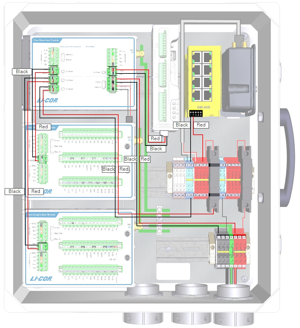
12 VDC power supply with Data Retention Module
With a 12 VDC power supply, you do not need to connect the DRM power out to the breaker or terminal strips because 12 VDC is within the limits of all components.
| From | Wire Color | To |
|---|---|---|
| DRM and DAqM Ground Lugs | yellow/green | Enclosure Ground Lug |
| DIN Terminal 11 (bottom) | black | DRM POWER IN GND (-) |
| DIN Terminal 13 (bottom) | red | DRM POWER IN +9-30 VDC (+) |
| DRM V1 Power GND | black | DAqM 1 GND (-) |
| DRM V1 Power +12V1 | red | DAqM 1 PWR (+) |
| DRM V2 Power GND | black | DAqM 2 GND(-) |
| DRM V2 Power +12V2 | red | DAqM 2 PWR (+) |
| DRM V4 Power GND | black | SmartFlux System (-) |
| DRM V4 Power +12 V4 | red | SmartFlux System (+) |
| DIN Terminal 12 (top) | black | Network Switch (-) |
| DIN Terminal 15 (top) | red | Network Switch (+) |
| DIN Terminal 11 (top) | black | Cellular/Satellite Modem (-) |
| DIN Terminal 13 (top) | red/white | Cellular/Satellite Modem (+) |

12 VDC power supply with no Data Retention Module
If your system does not have a Data Retention Module, the SmartFlux System will be powered from the enclosure power terminals rather than the DRM power outputs.
| From | Wire Color | To |
|---|---|---|
| DRM and DAqM Ground Lugs | yellow/green | Enclosure Ground Lug |
| DIN Terminal 11 (bottom) | black | DAqM GND (-) |
| DIN Terminal 13 (bottom) | red | DAqM PWR (+) |
| DIN Terminal 11 (top) | black | SmartFlux System GND (-) |
| DIN Terminal 14 (top) | red | SmartFlux System (+) |
| DIN Terminal 12 (top) | black | Network Switch (-) |
| DIN Terminal 15 (top) | red | Network Switch (+) |
| DIN Terminal 11 (top) | black | Cellular/Satellite Modem (-) |
| DIN Terminal 13 (top) | red/white | Cellular/Satellite Modem (+) |

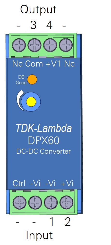
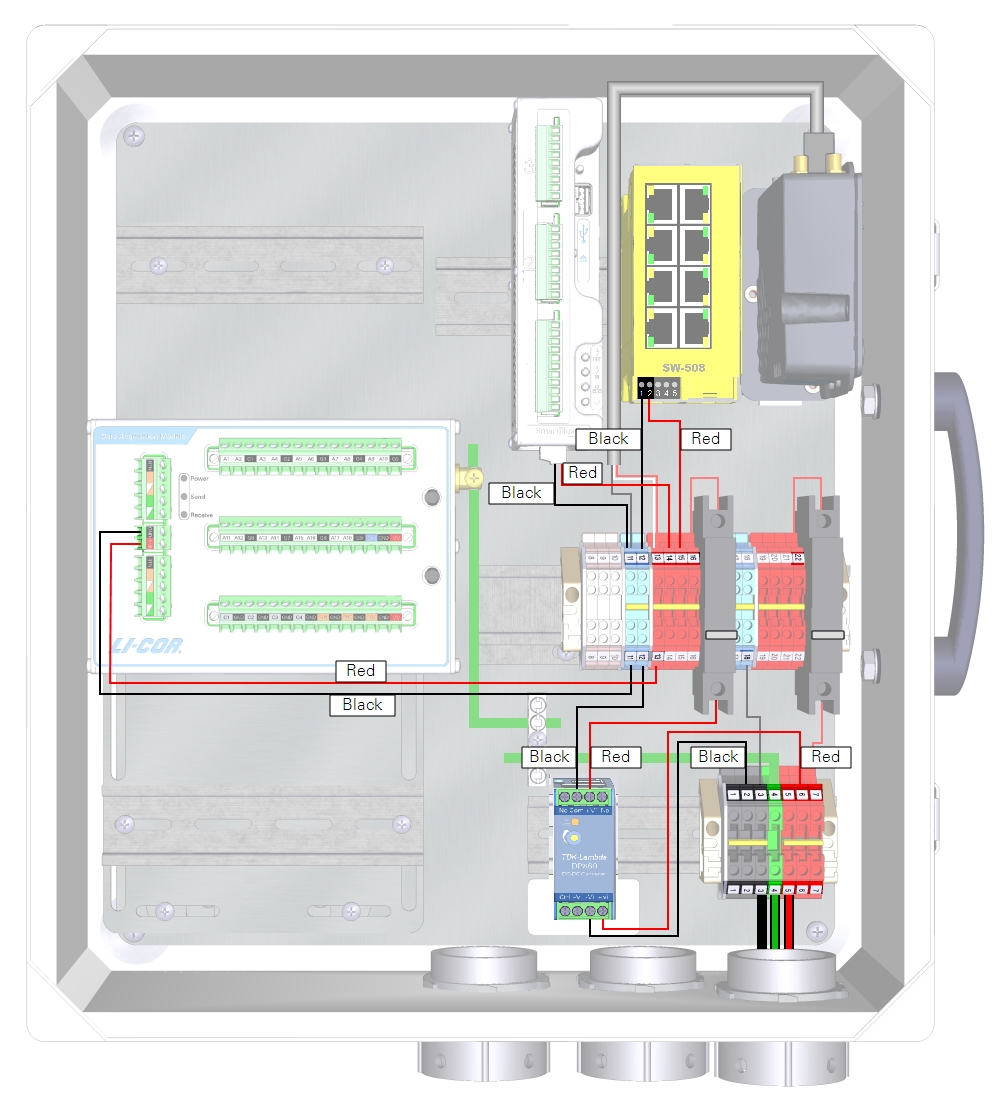
24 VDC power supply with the TDK-Lambda DC-DC converter
The TDK-Lambda DC-DC Converter (model DPX60) regulates output voltage to about 12 VDC, which makes it possible to power low-voltage devices from a 24 VDC solar power supply. The DC-DC converter should be used to power the left 10-amp accessory breaker (and the SmartFlux System) if you have a 24 VDC power supply and no DRM.
Full documentation for the TDK-Lambda DC-DC converter is available from the manufacturer's website: us.tdk-lambda.com/lp/products/dpx-series.htm.
The DC-DC converter mounts to a DIN rail in the lower right of the enclosure. Compress the spring the in the DIN clip and rotate the converter into place.
Connect the incoming power to the charge controller Input terminals (-Vi and +Vi) and connect the regulated power from the charge controller output terminals (COM and +V1) to the left breaker and DIN terminal 12. See Figure 2‑4 and Table 2‑6 for details.

Installing data cables
Communication is handled through RS-485, SDI-12, and Ethernet cables.
Connecting RS-485 data cables
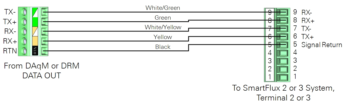
Each DRM and DAqM has RS-485 terminals labeled as DATA IN and DATA OUT. Although the communication is bidirectional, the labels describe the "flow" of readings through the unit toward the SmartFlux System. DATA IN receives biomet data from a DAqM. DATA OUT sends biomet data to a DRM, DAqM, or the SmartFlux System.
| From DATA OUT | Wire Color | To DATA IN or SmartFlux System |
|---|---|---|
| TX- | white/green | RX- |
| TX+ | green | RX+ |
| RX- | white/yellow | TX- |
| RX+ | yellow | TX+ |
| RTN | black | RTN or Signal Return |
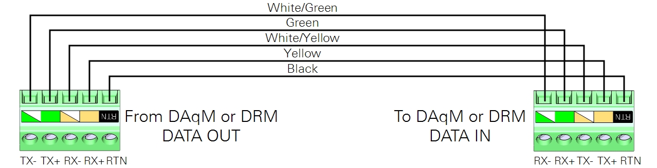
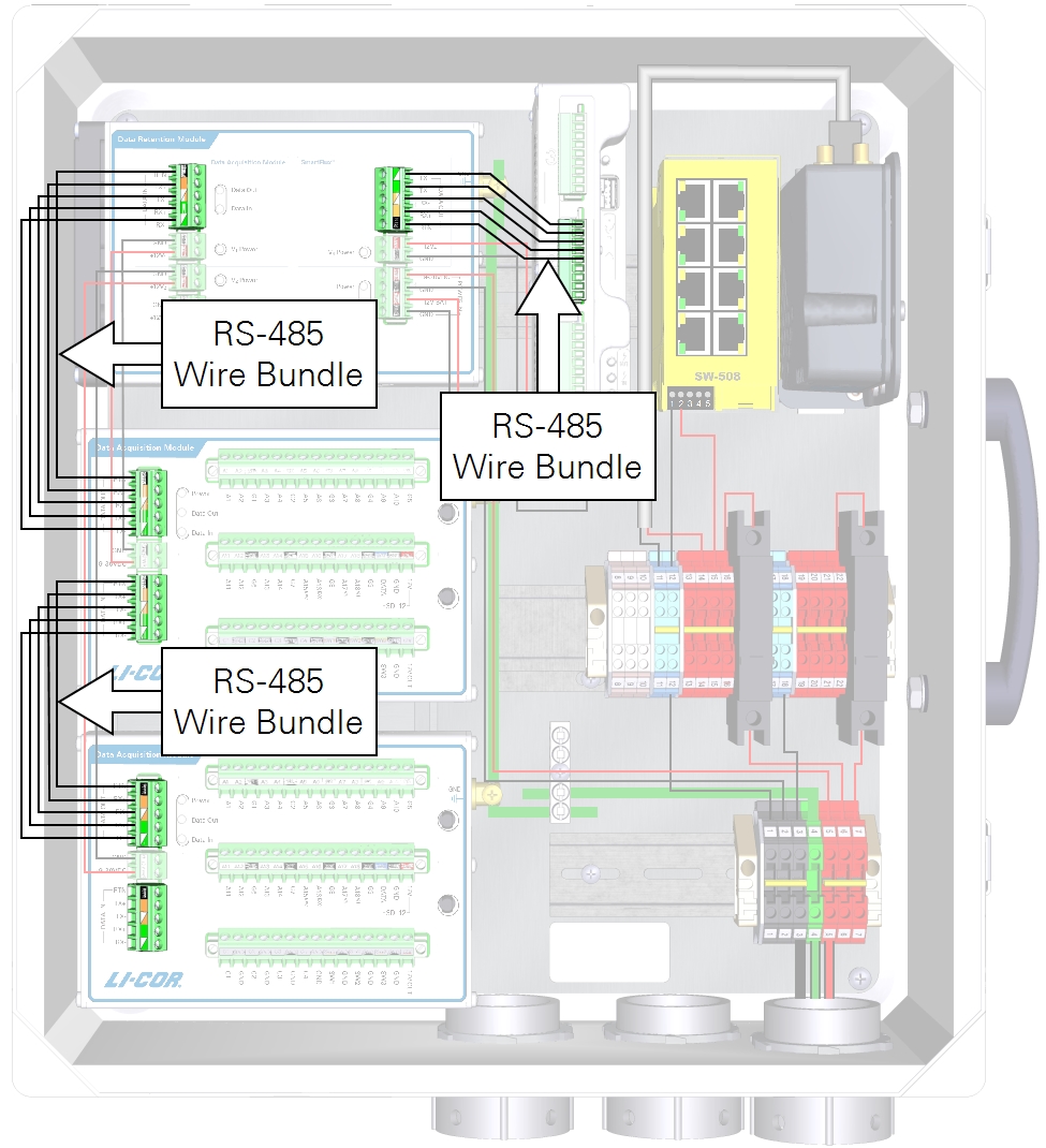
For a DRM and one or more DAqMs
Data cables for a system with two DAqMs are installed as shown in Figure 2‑7.
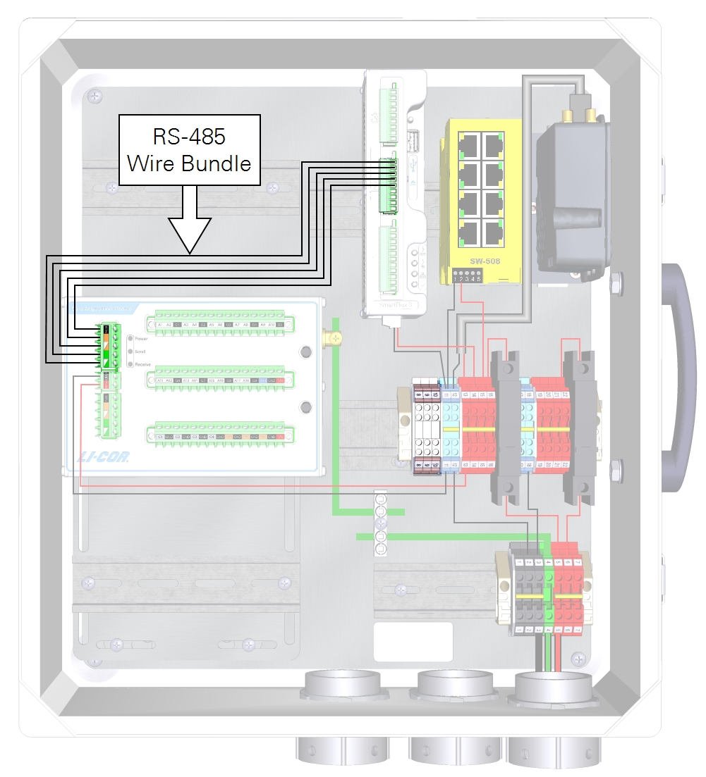
For a solitary DAqM
The data cable for a system with one DAqM and no DRM is installed as shown in Figure 2‑8.
Connecting SDI-12 data wire leads
Red, blue, and black wire leads connect the SDI-12 terminals to the to the DIN terminals.
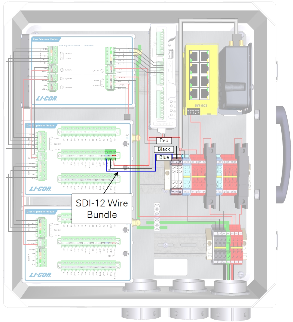
| From | Wire Color | To |
|---|---|---|
| SDI-12 DAT | blue | DIN Terminal 8 |
| SDI-12 GND | black | DIN Terminal 9 |
| SDI-12 12V | red | DIN Terminal 10 |
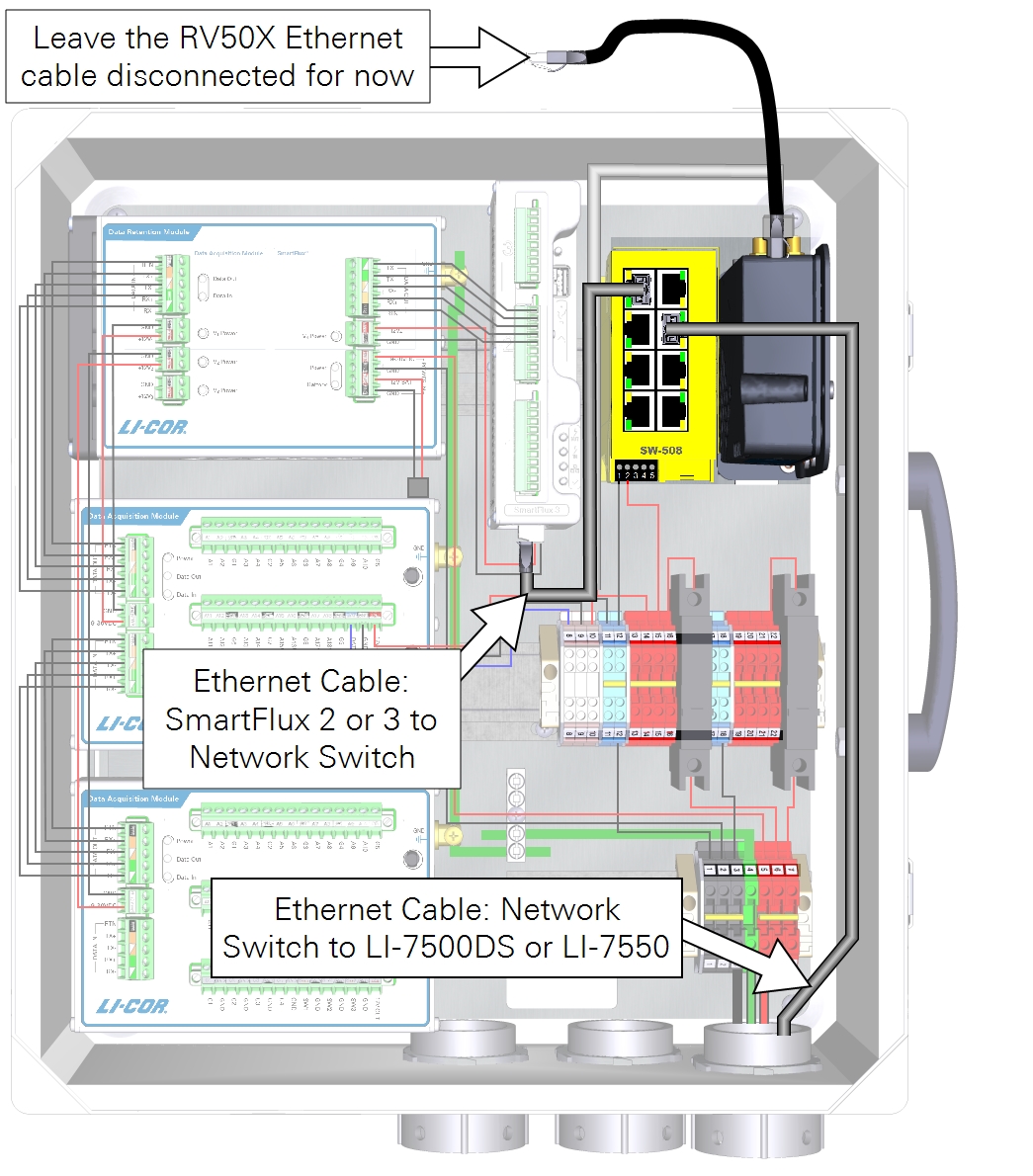
Connecting network data cables
Network cables connect the SmartFlux System and gas analyzer to the network switch. Vacant ports on the network switch are for other networked components, PhenoCam, LI-7700, or connecting a PC. If you have an RV50X cellular modem, leave its Ethernet cable disconnected until you are done configuring the instrument network.
Connecting PhenoCam data and power cables
Note: The StarDot NetCam SC (PhenoCam) has been replaced by a new model - the NetCamLIVE2. The NetCamLIVE2 is a direct replacement and is supported by SmartFlux 2 and 3 Systems (firmware v2.4.2 and newer).
The PhenoCam data cable connects to the network switch. The power wires connect to terminals in the enclosure.
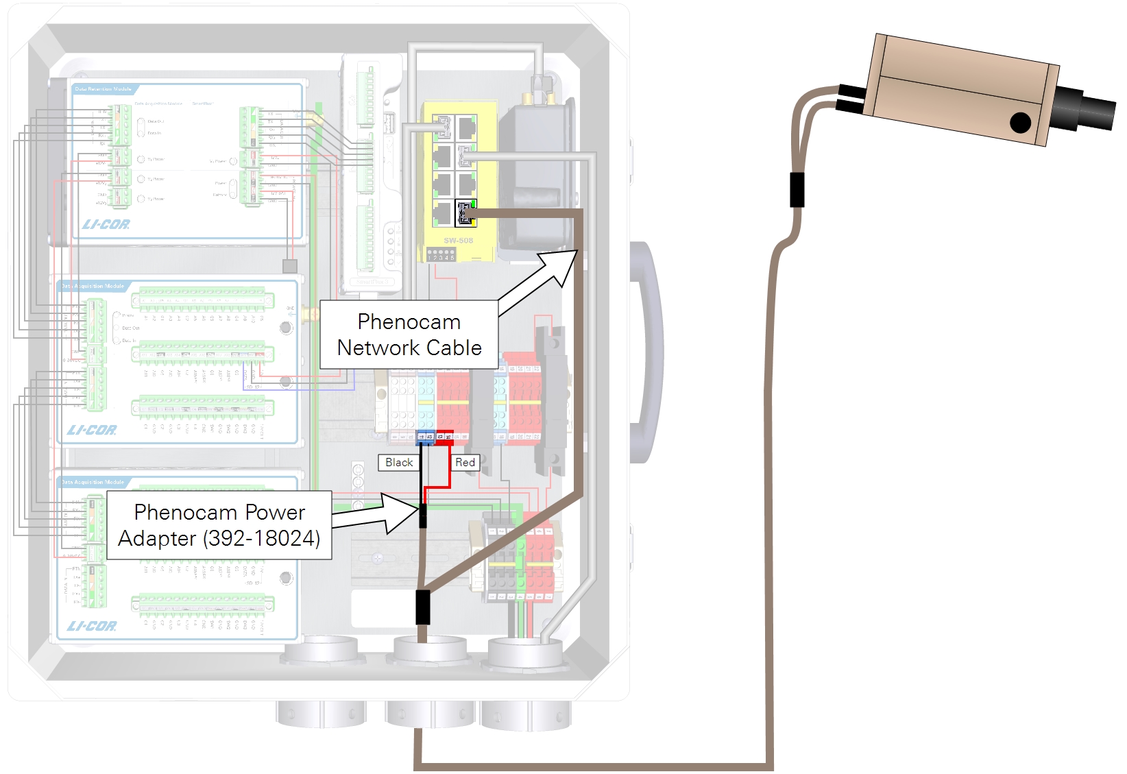
| From | Wire Color | To |
|---|---|---|
| PhenoCam Power (GND) | black | Terminal 11 |
| PhenoCam Power (+12 VDC) | red | Terminal 14 |