Here we describe how to connect sensors and enter calibration information for the four legacy sensor packages from LI-COR. Although we show how to connect the Stevens HydraProbes, they must be connected and configured one after the other until each one has a unique address.
Biomet Package 1
Part number 7900-101
Biomet Package 1 supports sensors listed in Table C‑1.
Table C‑1. Wiring for Biomet Package 1. If a sensor has wires that are not mentioned here, those wires are not used and can remain unconnected.
Measurement
Description
Wire Color
Terminal
Soil Heat Flux Plate 1 (Hukseflux HFP01)
Signal +
White
A1
Signal -
Green
A2
Shield
Black
G1
Soil Heat Flux Plate 2 (Hukseflux HFP01)
Signal +
White
A3
Signal -
Green
A4
Shield
Black
G2
Soil Heat Flux Plate 3 (Hukseflux HFP01)
Signal +
White
A5
Signal -
Green
A6
Shield
Black
G3
Net Radiation (NR Lite2)
Signal +
Red
A7
Signal -
Blue
A8
Shield
Black
G4
Air Temperature and Relative Humidity (Vaisala HMP155)
RH Signal
Yellow
A15
Temperature Signal
White
A16
Power
Blue
12V OUT
Signal Ground
Green
G8
Power Ground
Red
GND
Shield
Black
G7
Global Radiation (LI-CORLI-200R)
Anode
Brown
A17
Cathode
Blue
G9
Shield
Bare
G9
PPFD (LI-CORLI-190R)
Anode
Brown
A18
Cathode
Blue
G9
Shield
Bare
G9
Precipitation (Texas Electronics TR-5252M)
Switch
White/Clear
C1
Switch
Black
GND
Shield
Bare
GND
Soil Moisture and Temperature (Stevens HydraProbe)
Data
Blue
SDI-12 Data
Ground
Black
SDI-12 GND
Power
Red
SDI-12 12V
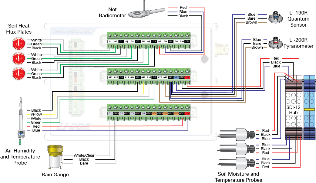
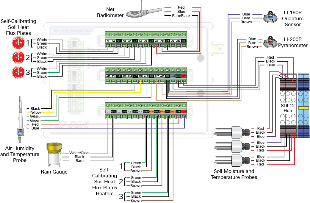
Wiring diagram
Figure C‑1. Schematic for Biomet Package 1.
Biomet Package 2
Part number 7900-102
Biomet Package 2 supports sensors listed in Table C‑2.
Wiring table
Table C‑2. Wiring for Biomet Package 2. If a sensor has wires that are not mentioned here, those wires are not used and can remain unconnected.
Measurement
Description
Wire Color
Terminal
Soil Heat Flux Plate 1 (Hukseflux HFP01)
Signal +
White
A1
Signal -
Green
A2
Shield
Black
G1
Soil Heat Flux Plate 2 (Hukseflux HFP01)
Signal +
White
A3
Signal -
Green
A4
Shield
Black
G2
Soil Heat Flux Plate 3 (Hukseflux HFP01)
Signal +
White
A5
Signal -
Green
A6
Shield
Black
G3
Net Radiation (Kipp & Zonen CNR4)
Upper Pyranometer +
Red
A7
Upper Pyranometer -
Blue
A8
Lower Pyranometer +
White
A9
Lower Pyranometer -
Black
A10
Upper Pyrgeometer +
Gray
A11
Upper Pyrgeometer -
Yellow
A12
Lower Pyrgeometer +
Brown
A13
Lower Pyrgeometer -
Green
A14
Shield
Bare/Black
G6
Net Radiometer Temperature (Kipp & Zonen CNR4)
Thermistor +
White
A15
Thermistor -
Black
G8
Shield
Bare/Black
G7
Air Temperature and Relative Humidity (Vaisala HMP155)
RH Signal
Yellow
A17
Temperature Signal
White
A16
Power
Blue
12V OUT
Signal Ground
Green
G8
Power Ground
Red
GND
Shield
Black
G7
PPFD (LI-CORLI-190R)
Anode
Brown
A18
Cathode
Blue
G9
Shield
Bare
G9
Soil Moisture and Temperature (Stevens HydraProbe)
Signal
Blue
SDI-12 DATA
Ground
Black
SDI-12 GND
Power
Red
SDI-12 12V
Precipitation (Texas Electronics TR-525M)
Switch
White/Clear
C1
Switch
Black
GND
Shield
Bare
GND
Net Radiometer Heater and Ventilation Unit (Kipp & Zonen CNF4)
Ventilator (+)
Yellow
SW2
Ventilator (-)
Brown
GND
Heater (+)
Black
SW1
Heater (+)
White
SW1
Heater (-)
Red
GND
Heater (-)
Blue
GND
Shield
Bare/Black
GND
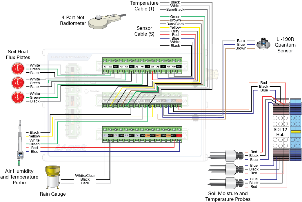
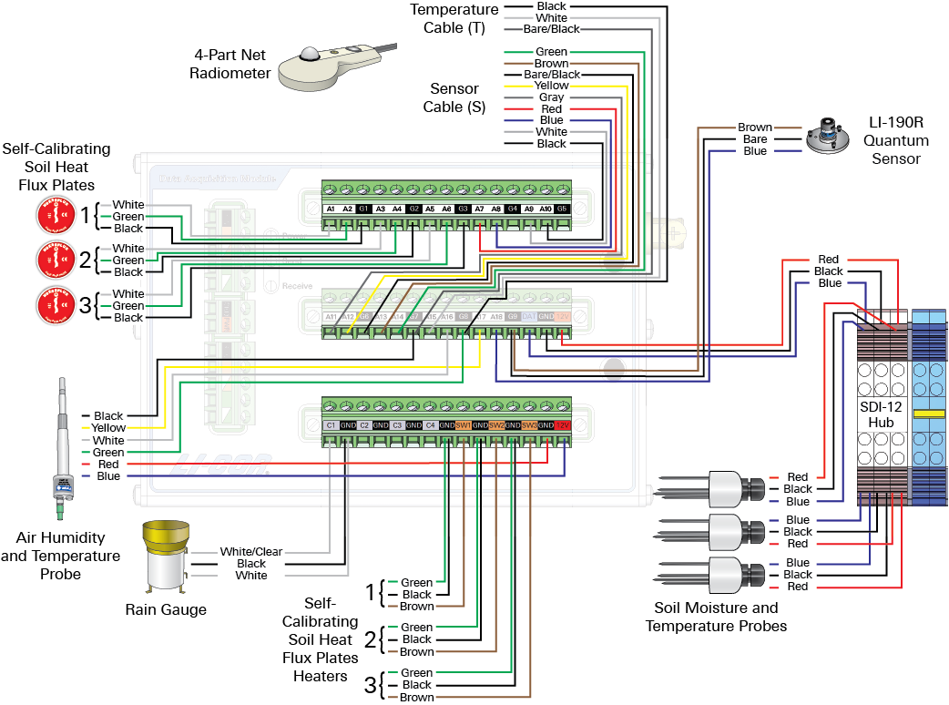
Wiring diagram
Figure C‑2. Schematic for Biomet Package 2.
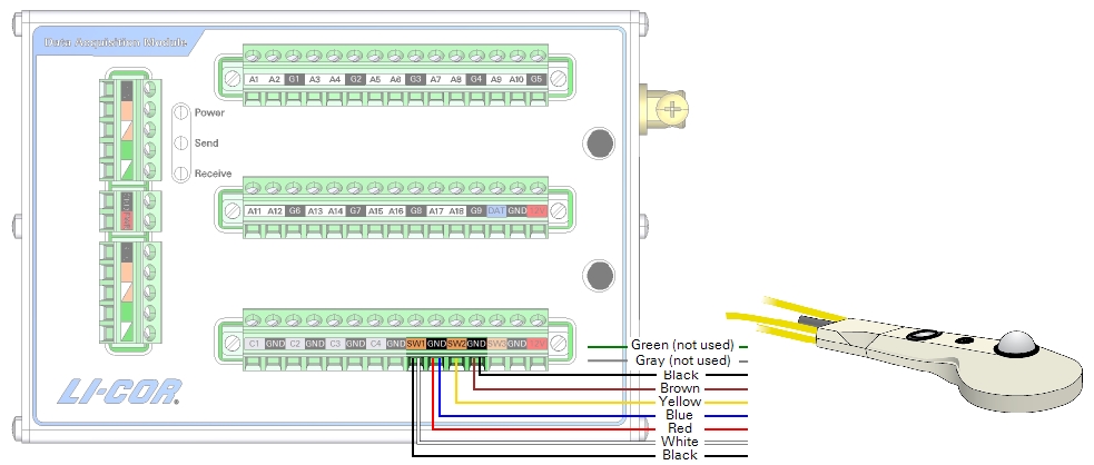
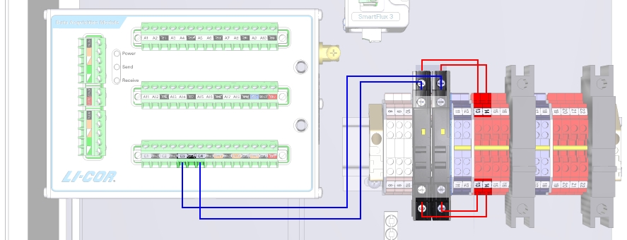
Connecting the optional CNF4
If you have two DAqMs, the CNF4 wires connect to the DAqM. The CNF4 is controlled by the DAqM's switched power supplies. The green and gray wires for the tachometer are not used.
Figure C‑3. Wiring the CNF4 with the Premium Package and Package 2.
Table C‑3. CNF4 connections.
CNF4 Wire
Color
Connection
Ventilator (+)
Yellow
SW2
Ventilator (-)
Brown
GND (SW2)
Tacho (+)
Green
Not used
Tacho (-)
Gray
Not used
Heater (+)
Black
SW1
Heater (+)
White
SW1
Heater (-)
Red
GND (SW1)
Heater (-)
Blue
GND (SW1)
Shield (black)
Black
GND (SW2)
Biomet Package 3
Part number 7900-103
Biomet Package 3 supports sensors given in table Table C‑4.
Wiring table
Table C‑4. Wiring for Biomet Package 3. If a sensor has wires that are not mentioned here, those wires are not used and can remain unconnected.
Measurement
Description
Wire Color
Terminal
Soil Heat Flux Plate 1 (Hukseflux HFP01SC)
Signal +
White
A1
Signal -
Green
A2
Shield
Black
G1
Soil Heat Flux 1 Calibration (Hukseflux HFP01SC)
Heater +
Brown
SW1
Heater -
Green
GND
Shield
Black
GND
Soil Heat Flux Plate 2 (Hukseflux HFP01SC)
Signal +
White
A3
Signal -
Green
A4
Shield
Black
G2
Soil Heat Flux 2 Calibration (Hukseflux HFP01SC)
Heater +
Brown
SW2
Heater -
Green
GND
Shield
Black
GND
Soil Heat Flux Plate 3 (Hukseflux HFP01SC)
Signal +
White
A5
Signal -
Green
A6
Shield
Black
G3
Soil Heat Flux 3 Calibration (Hukseflux HFP01SC)
Heater +
Brown
SW3
Heater -
Green
GND
Shield
Black
GND
Net Radiation (Kipp & Zonen NR Lite2)
Signal +
Red
A7
Signal -
Blue
A8
Shield
Bare/Black
G4
Air Temperature and Relative Humidity (Vaisala HMP155)
RH Signal
Yellow
A15
Temperature Signal
White
A16
Power
Blue
12V OUT
Signal Ground
Green
G8
Power Ground
Red
GND
Shield
Black
G8
Global Radiation (LI-CORLI-200R)
Anode
Brown
A17
Cathode
Blue
G9
Shield
Bare
G9
PPFD (LI-CORLI-190R)
Anode
Brown
A18
Cathode
Blue
G9
Shield
Bare
G9
Soil Moisture and Temperature (Stevens HydraProbe)
Signal
Blue
SDI-12 DATA
Ground
Black
SDI-12 GND
Power
Red
SDI-12 12V
Precipitation (Texas Electronics TR-525M)
Switch
White
C1
Switch
Black
GND
Shield
Bare
GND
Wiring diagram
Figure C‑4. Schematic for Biomet Package 3.
Biomet Package 4
Part number 7900-104
Biomet Package 4 supports the sensors given in Table C‑5.
Wiring table
Table C‑5. Wiring for Biomet Package 4. If a sensor has wires that are not mentioned here, those wires are not used and can remain unconnected.
Air Temperature and Relative Humidity (Vaisala HMP155)
RH Signal
Yellow
A17
Temperature Signal
White
A16
Power
Blue
12V OUT
Signal Ground
Green
G8
Power Ground
Red
GND
Shield
Black
G8
PPFD (LI-CORLI-190R)
Anode
Brown
A18
Cathode
Blue
G9
Shield
Bare
G9
Soil Moisture and Temperature (Stevens HydraProbe)
Signal
Blue
SDI-12 DATA
Ground
Black
SDI-12 GND
Power
Red
SDI-12 12V
Precipitation (Texas Electronic TR-525M)
Switch
White
C1
Switch
Black
GND
Shield
Bare
GND
Net Radiometer Heater and Ventilation Unit (Kipp & Zonen CNF4)
Ventilator (+)
Yellow
C4 (relay)
Ventilator (-)
Brown
GND
Heater (+)
Black
C3 (relay)
Heater (+)
White
C3 (relay)
Heater (-)
Red
GND
Heater (-)
Blue
GND
Shield
Bare/Black
GND
Wiring diagram
Figure C‑5. Schematic for Biomet Package 4.
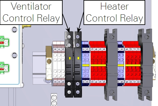
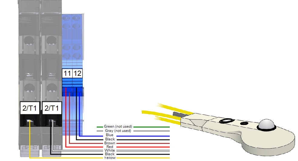
Connecting the optional CNF4
For Sensor Package 4, you'll need to install two relays and wire leads, which are required to actuate the relays and provide the timer-controlled power to the CNF4. The CNF4 wires connect to the relays and DIN terminals. The green and gray wires for the tachometer are not used.
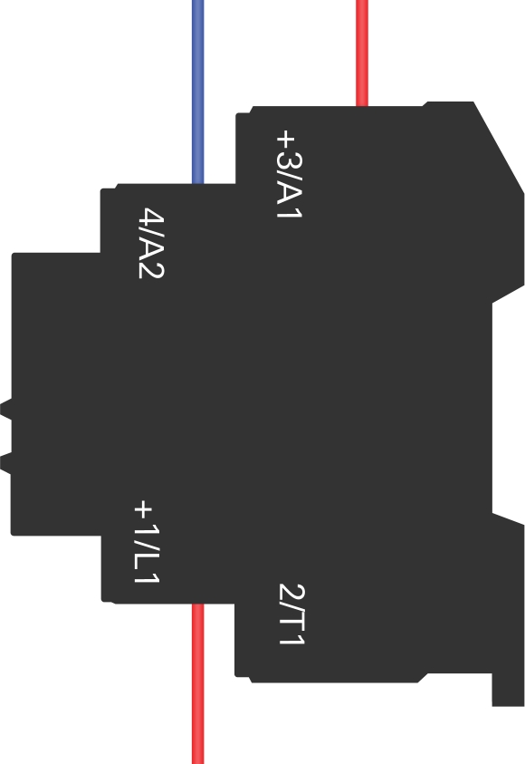
Description
Color
Terminals Connected
Ventilator Relay Control
Blue
C4 to Left Relay 4/A2
Ventilator Relay Power
Red
13 to Left Relay +3/A1
Ventilator Power
Red
13 to Left Relay +1/L1
Heater Relay Control
Blue
C3 to Right Relay 4/A2
Heater Relay Power
Red
14 to Right Relay +3/A1
Heater Power
Red
14 to Right Relay +1/L1
Figure C‑6. Wiring the CNF4 with Sensor Package 4.