Using the Hukseflux NR01 Net Radiometer in Biomet Systems
Printable PDF: Using the Hukseflux NR01 Net Radiometer in Biomet Systems
(Installing-NR01-18869.pdf)
Download this content as a pdf that can be saved to your computer or printed.
The Hukseflux NR01 Net Radiometer (part number 7900-146) measures incoming (downwelling) and reflected (upwelling) radiation in two spectral bands. The NR01 is supported by the Standard package. Be sure to read the manufacturer's instructions before using the NR01.
Siting the net radiometer
Install the net radiometer so its view is unobstructed by adjacent structures, trees, and the meteorological station. Select a location that is away from heat sources. Orient the sensor with the sensing element pointing toward the equator to minimize shading from surrounding elements. Mount the sensor at least 1.5 m above the plant canopy.
Mounting the net radiometer
Mount the radiometer perpendicular to the cross-arm using a cross-over fitting in accordance with the instructions from the manufacturer. Orient the net radiometer boom toward the equator to ensure that it is not covered by a shadow of other things on the tower.
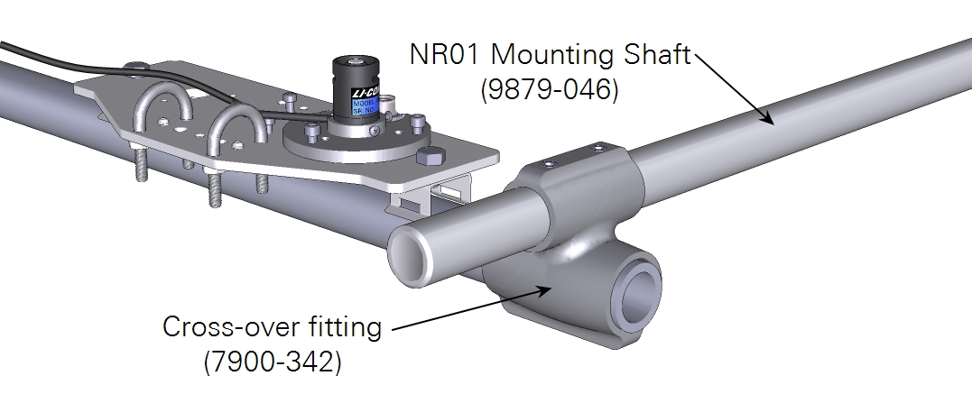
Tighten the pins securely.
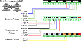
Wiring the net radiometer
The NR01 is supported by the Standard program and custom programs. The following schematic and table show wiring for the standard program.
| Cable | Description | Wire Color | Terminal |
|---|---|---|---|
| Net Radiation | Upper Pyranometer + | Red | A7 |
| Upper Pyranometer - | Blue | A8 | |
| Ground | Black | G4 | |
| Lower Pyranometer + | White | A9 | |
| Lower Pyranometer - | Green | A10 | |
| Upper Pyrgeometer + | Brown | A11 | |
| Upper Pyrgeometer - | Yellow | A12 | |
| Lower Pyrgeometer + | Pink | A13 | |
| Lower Pyrgeometer - | Gray | A14 | |
| Temperature | Ground | Black | G6 |
| Thermistor + | Red | A15 | |
| Thermistor + | White | A15 | |
| Thermistor - | Blue | G7 | |
| Thermistor - | Green | G7 | |
| Heater Ground | Yellow | GND | |
| Heater Power | Brown | SW1 |
Retrieving Data
The SmartFlux System will log these data in compressed files for processing by EddyPro Software and evaluation by Tovi Software. Data are stored on the USB drive on the SmartFlux System. Refer to the Data Acquisition System instruction manual for details.
Maintenance
The probe is a low maintenance sensor and little care is required as long as the sensor is performing as expected. If the sensor is providing questionable data:
- Check the connections to the datalogger and ensure that they are correct and secure.
- Check the cables for damage.
- Ensure that the datalogger has an adequate power supply.