The Kipp & Zonen NR Lite2 net radiometer (part number 7900-140) measures net radiation and outputs a single analog signal. Here we provide basic installation and operation guidelines for using the NR Lite2 in a LI-COR biomet data acquisition systems. Be sure to read the manufacturer's instructions before using the NR Lite2.
| NR Lite2 Specifications | |
|---|---|
| Spectral range: | 0.2 to 100 μm |
| Energy range: | -200 to 1000 W/m2 |
| Response time: | <20 s @ 63% |
| Nominal sensitivity: | 10 μV/Wm2 |
| Directional error: | <3% up to 60° |
| Sensor asymmetry: | <15% |
| Operating temperature range: | -30 to +70 °C |
| Cable length: | 15 meters |
Siting the net radiometer
Install the net radiometer so its upward and downward views are unobstructed by adjacent structures, trees, and the meteorological station. Select a location that is away from heat sources or reflective surfaces.
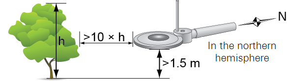
Orient the sensor with the sensing element pointing toward the equator to minimize shading from surrounding elements. Mount the sensor at least 1.5 m above the plant canopy. Install the bird-deterrent stick.
Mounting the net radiometer
The NR Lite2 mounts to the 7900-350 Radiation Sensor Mount, which can be affixed to a horizontal cross-arm.
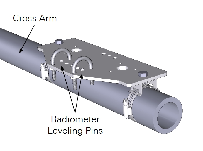
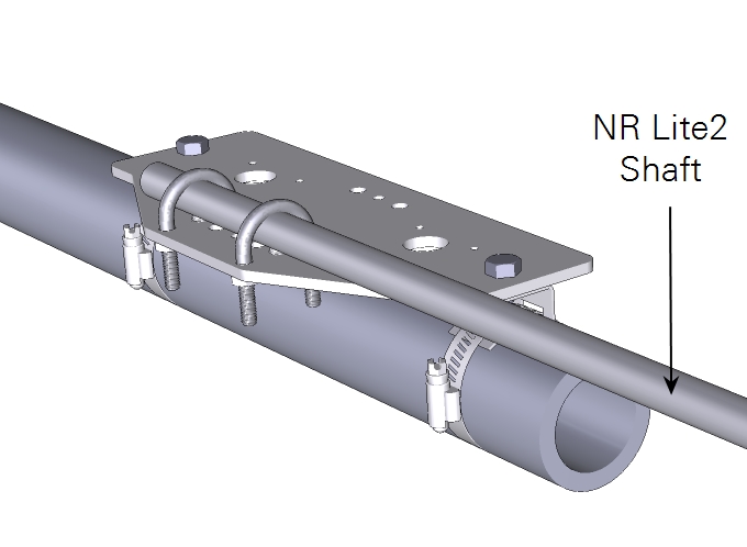
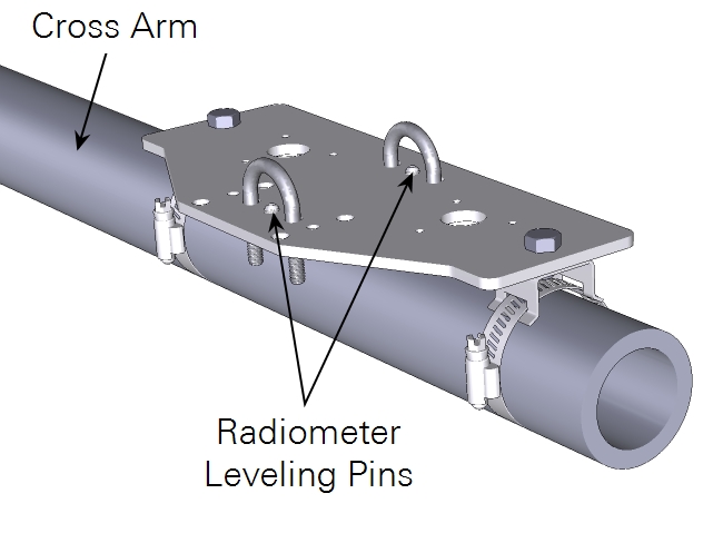
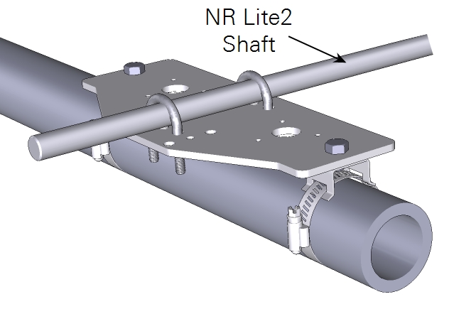
Attach the mounting brackets and band clamps to the plate. Tighten the band clamps around the cross arm. Attach the U-bolts to secure the radiometer shaft. Rotate the radiometer as needed and adjust the leveling pins to level the sensor. Tighten nuts to secure the U-bolts.
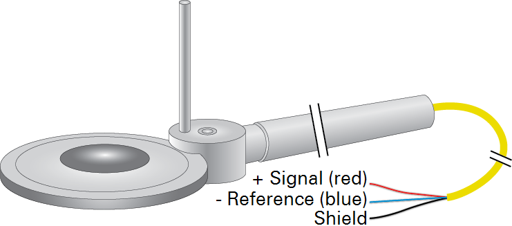
Wiring the net radiometer
The NR Lite2 Net Radiometer is supported by the Basic Program and Programs 1 and 3.
| Description | Color | Basic | Programs 1 and 3 |
|---|---|---|---|
| Signal (+) | Red | A11 | A7 |
| Signal (-) | Blue | G6 | A8 |
| Ground | Black | G6 | G4 |
Entering the calibration constant
The calibration factor is printed on the sensor and also included with the product documentation. It indicates the sensitivity of the radiometer. Confirm that the serial number on the sensor corresponds with the serial number on the calibration certificate. The calibration factor (sensitivity), which is in units of μV/W m-2, should be entered directly into the datalogger software.
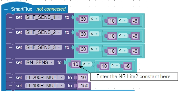
Save the configuration and push the file to the data acquisition system after entering the remaining calibration information. No additional steps are required to use the NR Lite2.
Retrieving data
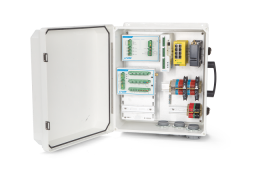
The SmartFlux System will log these data in compressed files for processing by EddyPro Software and evaluation by Tovi Software. Data are stored on the USB drive on the SmartFlux System. Refer to the Data Acquisition System instruction manual for details.
Maintenance
Keep the sensor clean. It can be cleaned using water or alcohol. Check to be sure that the instrument is level. Recalibrate the sensor every 2 years. Contact the manufacturer for more information.