Installing Soil Heat Flux Plates in Biomet Systems
Printable PDF: Installing Soil Heat Flux Plates in Biomet Systems
(Installing-SHF-Plates-12671.pdf))
Download this content as a pdf that can be saved to your computer or printed.
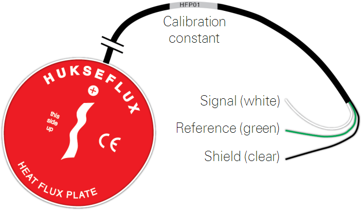
Hukseflux HFP01 soil heat flux plates (part number 7900-150) measure heat exchange across the plane of the plate. Here we provide basic installation and operation guidelines for using the HFP01 in LI-COR biomet data acquisition systems. Be sure to read the manufacturer's instructions before using the HFP01 Soil Heat Flux Plates.
| HFP01 Specifications: | |
|---|---|
| Nominal sensitivity: | 50 μV/W/m2 |
| Typical range: | -100 to 300 W/m2 |
| Nominal resistance: | 2 ohms |
| Temperature range: | -30 to + 70 °C |
| Sensor thermal resistance: | <6.25 x 10⁻³ km2/W |
| Measurement range: | ±2000 W/m2 |
| Expected accuracy: | Within -5% to +15% in most soils |
| Power consumption: | 0 W |
| Cable length: | 15 meters |
Siting soil heat flux plates
In a typical installation, three or more heat flux plates are needed in order to ensure good representation of the site.
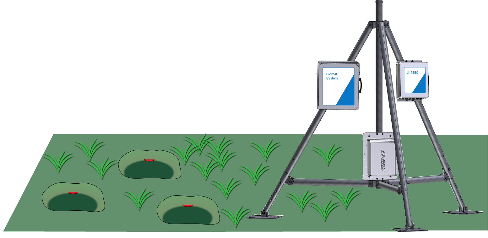
Place each heat flux plate in a shallow pit in soil that is representative of the site. More sensors may be needed if the soil is highly variable. Heat flux plates and soil moisture sensors and temperature sensors can be placed in the same excavation.
Burying the heat flux plates
Excavate a small hole with a smooth, undisturbed side. Keep the excavated soil as an intact block if possible. Make a horizontal slit in the smooth side of the excavation 5 cm below the soil surface.
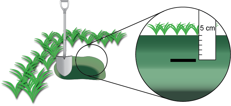
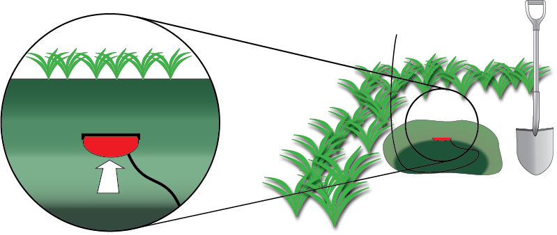
With the red side facing up toward the sky, gently insert the heat flux plate in the slit until it is completely covered by soil. Be sure the plate is in full contact with the soil and that there are no air pockets around it. Bury a length of the sensor leads to prevent thermal conduction through the wires. Fill the hole with the excavated soil.
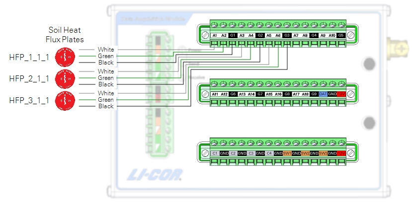
Wiring soil heat flux plates
| Description | Color | Plate 1 | Plate 2 | Plate 3 |
|---|---|---|---|---|
| Signal (+) | White | A1 | A3 | A5 |
| Signal (-) | Green | A2 | A4 | A6 |
| Sheild | Black | G1 | G2 | G3 |
Entering the calibration data
Each soil heat flux plate has a unique calibration constant that is provided by Hukseflux. It is printed on the sensor's cable label and given on a calibration sheet provided with the sensor. The calibration factor (sensitivity) for each sensor, which is in units of μV/W m-2, should be entered directly into the Blueprint Utility.
Select a program (Biomet Library) and then enter the calibration multipliers.
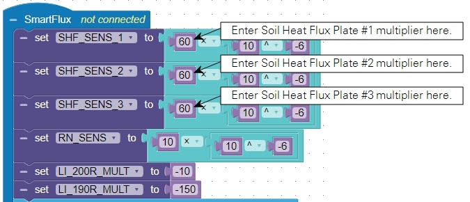
Save the configuration and push the file to the data acquisition system after entering the remaining calibration information.
Retrieving data
The SmartFlux System will log these data in compressed files for processing by EddyPro Software and evaluation by Tovi Software. Data are stored on the USB drive on the SmartFlux System. Refer to the Data Acquisition System instruction manual for details.
Maintenance
- Check the your data regularly to ensure that you are recording plausible values.
- Periodically check the wire leads for rodent damage.
- Recalibrate the sensors every two years according to the manufacturer's instructions.