Printable PDF: Installing Stevens HydraProbes in Biomet Systems
(Installing-Stevens-HydraProbes-14577.pdf)
Download this content as a pdf that can be saved to your computer or printed.
The Stevens HydraProbes (part number 7900-170) measure soil moisture, temperature and other parameters. They transmit data using the SDI-12 communication protocol. This document provides basic installation and operation guidelines for using the HydraProbe in LI-COR biomet data acquisition systems.
| Hydra Probe II | |
|---|---|
| Operating temperature range: | -40 to 75 °C |
| Voltage range: | 9 to 20 VDC |
| Measurement range: | 0.0 to Saturation |
| Accuracy: | ±0.03 m3/m3 |
| Power requirements: | <1 mA idle; 30 mA active |
| Cable lengths: | 15 meters |
Siting the HydraProbes
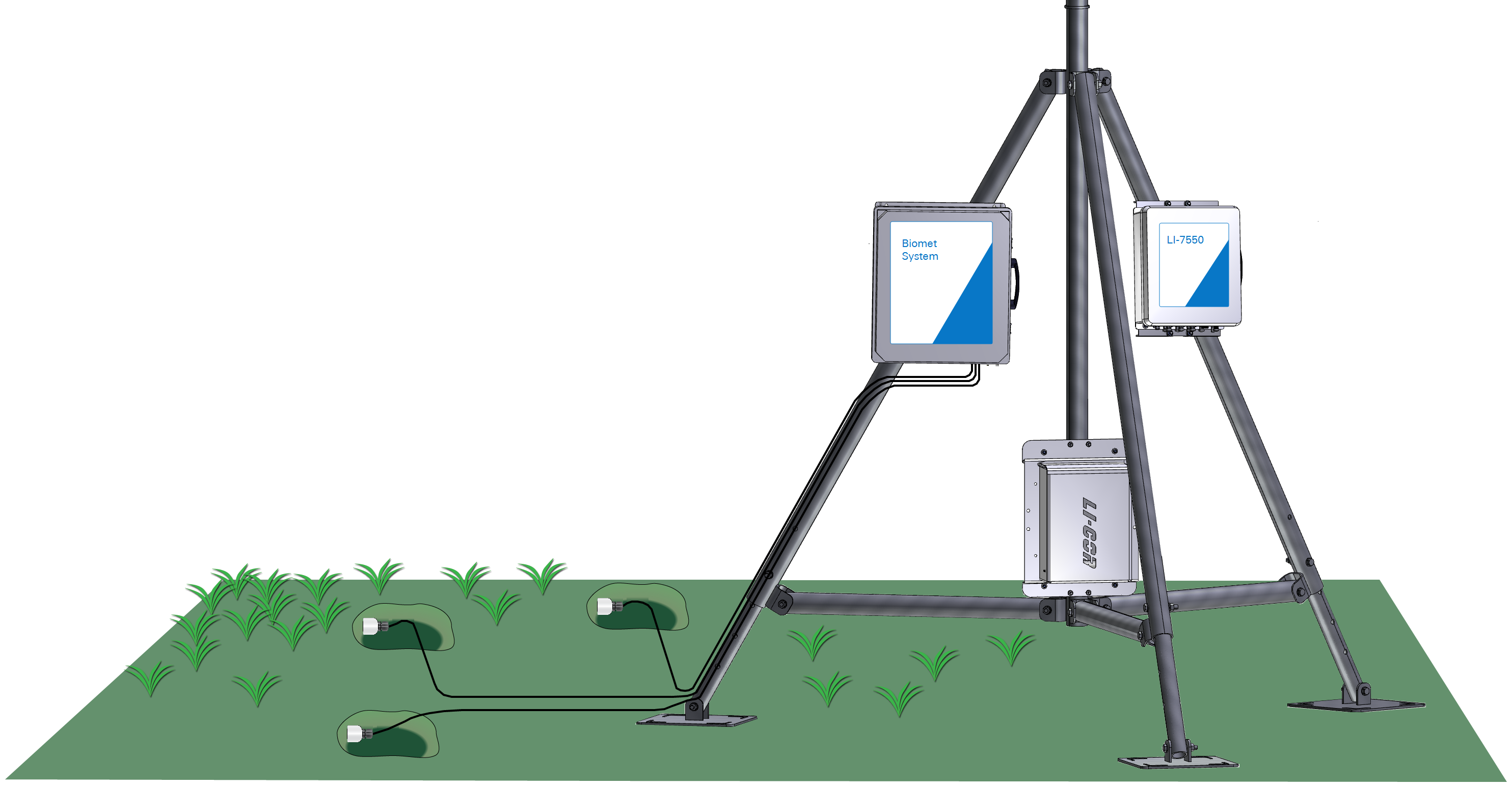
Three or more probes may be required for some sites. Place the probes in undisturbed soil that is representative of the site. Probes can be inserted directly into the soil surface or inserted into the soil in a pit.
Burying the HydraProbes
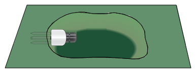
Install the probes at a depth of 5 cm below the soil surface. Press the probe into the soil until the base of the tines is flush with the soil. Be especially careful to avoid creating air pockets when inserting the probe. Air pockets around the tines will reduce the accuracy of measurements.
Setting the SDI-12 addresses
SDI-12 (Serial Digital Interface) communication is a standard for interfacing data recorders with microprocessor-based sensors. The SDI protocol enables data from multiple sensors to be recorded over a single SDI connection. In order to work, each SDI sensor must have a unique address. This section describes how to address the HydraProbe with the data acquisition system.
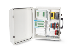
The enclosure includes connections for three soil probes. If you want to add more than three soil probes, the required modular terminals and resistors can be purchased directly from LI-COR. Contact us for more information.
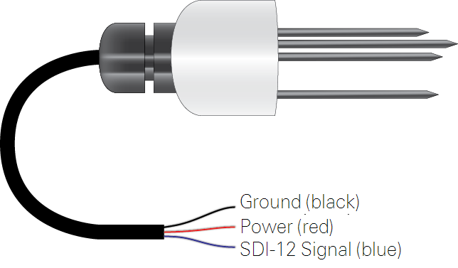
- Connect the first HydraProbe sensor (the one you will designate as Sensor 1).
-
Color Description Terminal DIN Terminal Blue Signal SDI-12 Signal 8 Black Ground SDI-12 Ground 9 Red Power SDI-12 12 VDC 10 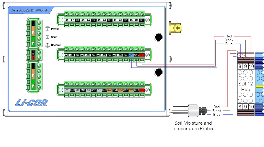
- Address the first sensor.
- In Blueprint Utility, click SDI-12 Console. Enter the command of 0A1 and click Send (the command indicates set sensor 0 address (A) to 1). The datalogger will find the sensor, and set the address to 1.
- Repeat steps 1 and 2 for the other sensors 2 and 3.
- The commands 0A2 and 0A3 are for sensors 2 and 3 respectively.
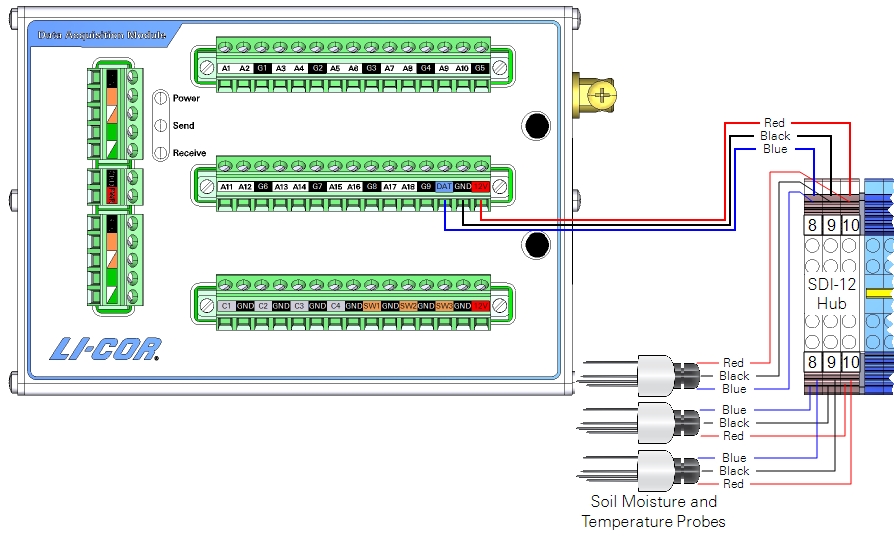
- Set the soil type.
To set the soil type for sensor 1, enter the following: 1XW_SOIL_<G/O/R> then click send. The probe will reply: 1<G/O/R>, where the letter indicates the soil type of G for general, O for organic, or R for rockwool.
You'll need to save the configuration and push the file to the data acquisition system after configuring SDI-12 sensors.
Retrieving data
The SmartFlux System will log these data in compressed files for processing by EddyPro Software and evaluation by Tovi Software. Data are stored on the USB drive on the SmartFlux System. Refer to the Data Acquisition System instruction manual for details.
Maintenance
Stevens HydraProbes are sealed at the factory. They do not require routine maintenance. Be mindful of the following points:
- Do not attempt to disassemble the sensor. This will damage the factory seal and invalidate the warranty.
- Do not remove the HydraProbe from soil by pulling on the cable.
- Do not attempt to straighten a bent rod while it is attached to the probe. Remove the bent rod before straightening.