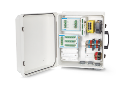
The Texas Electronics TR-525M tipping bucket rain gauge (part number 7900-160) measures liquid precipitation using a tipping bucket and momentary switch. Here we describe how to use the TR-525M rain gauge in LI-COR biomet data acquisition systems. Be sure to read the manufacturer's instructions before using the rain gauge.
| Precipitation Gauge TR-525M Specifications: | |
|---|---|
| Resolution: | 0.1 mm |
| Accuracy: | 1.0% up to 50 mm/hr |
| Collector diameter: | 245 mm |
| Operating temperature range: | 0 to 50° C |
| Switch: | Momentary potted reed |
| Switch rating: | 30 VDC @ 2A |
| Switch closure time: | 135 ms |
| Cable lengths: | 15, 25, and 50 meters |
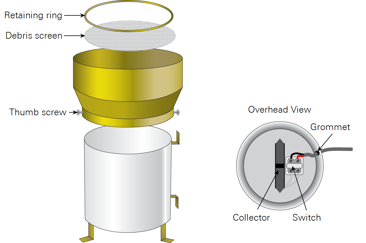
Assembling the rain gauge
The rain gauge is shipped partially assembled. To connect the cable, route it through the grommet in the side of the rain gauge, remove the black rubber cover from the cable connector, and connect the cable wires to the internal magnetic switch. Polarity doesn't matter in this case. Reattach the rubber cover.
Important: Be sure that the collector is not held in the center position by magnetic attraction. It must be tipped to one side or the other. If it is tied down, remove the string or rubber band.
Insert the screen into the funnel and secure it by pressing in the retaining ring. Secure the funnel to the body of the gauge by tightening the two thumb screws.
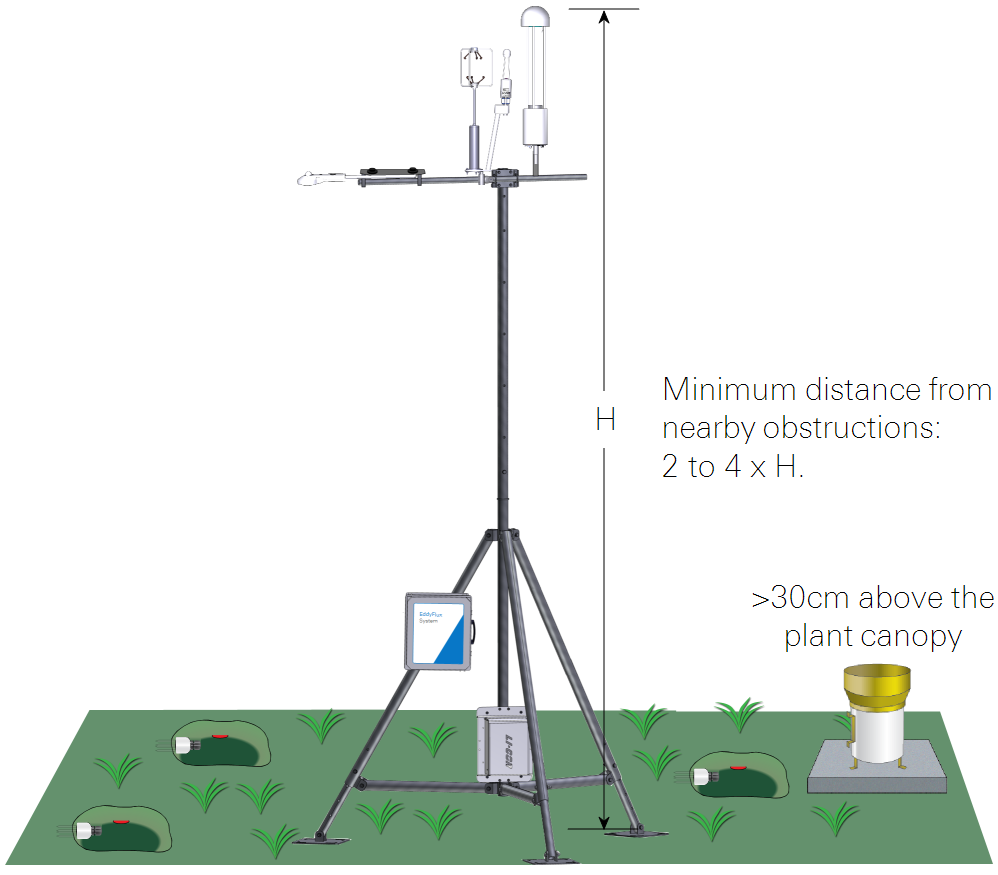
Siting the rain gauge
Select a level location that is representative of the surrounding area. The funnel should be >30 cm above the plant canopy. The minimum distance from nearby obstructions is at least 2 times the height of the obstruction.
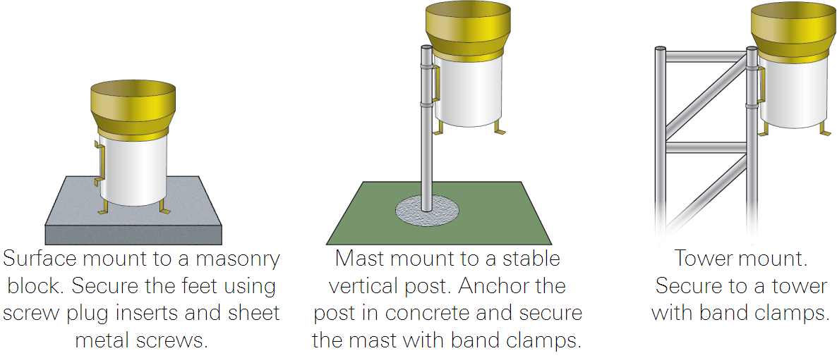
Mounting the rain gauge
Make sure the funnel is level and the body is plumb. Be sure the tipping bucket can move freely from side to side and that it is not stuck in the center position. If using a mast mount, be sure the mast is secure, stable, and plumb.
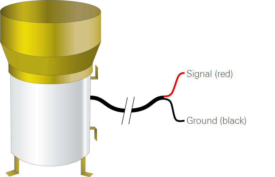
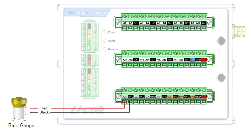
Wiring the rain gauge to the data acquisition module
Connect the wire leads as described below. No additional configuration is necessary.
| Lead Description | Color | Terminal |
|---|---|---|
| Signal | Red | C1 |
| Ground | Black | GND |
Save the configuration and push the file to the data acquisition system after entering the remaining calibration information.
Retrieving data
The SmartFlux System will log these data in compressed files for processing by EddyPro Software and evaluation by Tovi Software. Data are stored on the USB drive on the SmartFlux System. Refer to the Data Acquisition System instruction manual for details.
Maintenance
Check the device regularly and keep the funnel and bucket clean and free of foreign materials such as dust, debris, and insects. Check the field calibration periodically using the field calibration kit from Texas Electronics or using a home-made field calibration kit, as described in the manufacturer's instructions.