Specifications
Data acquisition module
Configuration interface: Windows® graphical programming
Analog inputs: Up to 18 single-ended or up to 9 (each differential input occupies two single-ended inputs). User-settable range of ±20 mV, ±40 mV, ±80 mV, ±160 mV, ±320 mV, ±640 mV, ±1.25 V, ±2.5 V, and ±5 V
With built-in excitation voltage: 2 (5 V, 25 mA excitation)
With selectable current or voltage: 2 (User-settable range of ±2.5 µA, ±25 µA, and ±250 µA)
Resolution: 24 bit
SDI-12 inputs
Digital inputs/outputs: 4
Output: 5 V logic
Input: 5 V or 3.3 V logic
Switched voltage outputs: 3
Output voltage: 9 to 30 VDC
Output current: Up to 1 A, with current sensing
12V excitation voltage output: 1
Up to 200 mA @ 25 °C
Sampling rate: 1 measurement per second
Time Synchronization: Within 3 seconds of GPS clock in SmartFlux
Communications protocol: RS-485 input and output into SmartFlux for storage and processing with EddyPro
Power requirements: +9 to 30 VDC
Power consumption: 0.85 W (@9 V) to 1.3 W (@30 V)
Dimensions: 17 cm × 10.9 cm × 7 cm (W × H × D)
Weight: 0.52 kg
Data retention module
Communication protocol: RS-485 input and output into SmartFlux for storage and processing with EddyPro
Power outputs (DC-DC converter): 4 (12 VDC maximum)
Maximum per output: 2 Amps (24 watts) up to 5 amps total for all outputs
Total maximum power out: 5 amps (60 watts)
Protection: Self-resetting fuses; Near instantaneous reset with brief overcurrent, 1 minute delay after major short.
Power requirements: +9 to 32 VDC
Back-up Battery Charger: Recharges the backup battery when main power is on and switches to the backup if main power fails.
Data storage: 32 MB; Backup biomet data collection capacity generally depends on backup battery capacity. With a large enough battery, the Data Retention Module can store over one month of backup data.
Dimensions: 17 cm × 10.9 cm × 7 cm (W × H × D; not including battery)
Weight: 0.52 kg (not including battery)
Backup battery
Type: Lead Acid
Output: 12 VDC; 7.2 Amp Hour
Fuse: 10 Amp, quick acting
Weight: 2.5 kg
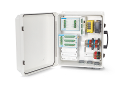
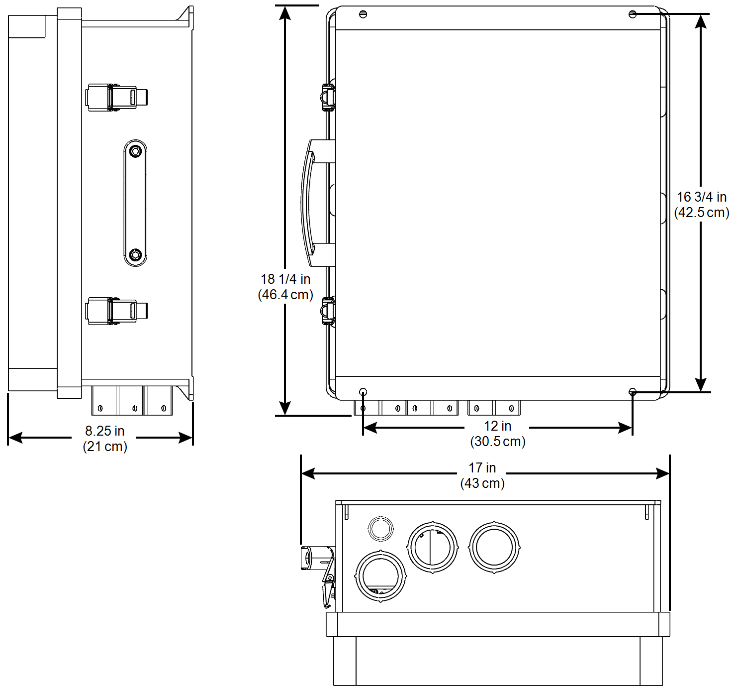
EddyFlux system enclosure
Dimensions: 39 cm × 45 cm × 21 cm (W × H × D)
Weight: 7.71 kg
Compatible wire gauges: 26 AWG to 14 AWG
Biomet package power requirements
The power requirements for each sensor package depend upon the components in use.
Basic Biomet Package: Normally 1.6 W; Maximum 3.9 W
Standard Biomet Package: Normally 1.6 W; Maximum 3.9 W
Advanced Biomet Package: Normally 2.3 W; Maximum 20 W
Biomet Package 1: Normally 1.6 W; Maximum 3.9 W
Biomet Package 2: Normally 1.6 W; Maximum 3.9 W; 20 W with CNF4
Biomet Package 3: Normally 2.3 W; Maximum 4.8W
Biomet Package 4: Normally 2.3 W; Maximum 4.8 W; 20 W with CNF4
Blueprint Utility software
OS System requirements: Windows 7 or newer, 64-bit architecture; macOS, 64-bit architecture.
RAM: 4 GB minimum; 8 GB recommended
Processor: Intel Core 2 - 2.0 GHz minimum; Intel i3 - 2.6 GHz or better recommended
Input specifications
Detailed specifications for DRM inputs are given below.
Single-ended voltage inputs
Table E‑1 gives the general specifications for the single-ended voltage inputs. The RMS noise statistics were obtained from a single DAqM at 25 °C and were based on n = 100 points sampled at 1 Hz with the input shorted to GND. The absolute accuracy specifications apply over the entire -40 to 50 °C operating range. The accuracy column specifies the error of the measurement as a percentage of the measurement reading plus an offset. The absolute gain accuracy was calculated by summing the absolute values of the maximum measured box-fitted temperature coefficient of five DAqMs over a -40 to 50 °C (-7.2 ppm/°C × 90 °C = 648 ppm) operating range plus the 50 ppm gain accuracy of the Agilent 34465A DMM used for voltage calibration plus a 100 ppm gain error tolerance from the gain calibration verification, |-648| + |100| + |50| ≈ 800 ppm (0.08%). Offsets were measured on all 18 single-ended voltage channels shorted with low thermal EMF silver clad solid copper wire to their matching GND of four DAqMs over a -40 to 50 °C operating range. The offsets were computed by summing the absolute value of the mean offset over temperature plus 6 standard deviations rounded up to the nearest µV.
Differential voltage inputs
Table E‑2 gives the general specifications for the differential voltage inputs. The offset, gain, and noise specifications and testing parameters are equivalent to those used for the single-ended voltage inputs.
Differential voltage inputs with 100 kΩ pull-down enabled
Table E‑3 gives the general specifications for the differential voltage inputs with the 100 kΩ pull-downs enabled. The offset, gain, and noise specifications and testing parameters are equivalent to those used for the differential voltage inputs with the exception that the differential voltage input pairs were shorted together but not shorted to GND.
Thermistor input current
Table E‑4 gives the general specifications for the thermistor inputs. The RMS noise statistics were obtained from a single DAqM at 25 °C and were based on n = 100 points sampled at 1 Hz with the input floating and excited with 5 V. The absolute gain accuracy was calculated by summing the absolute values of the temperature coefficient over a -40 to 50 °C (25.9 ppm °C 90 °C = 2,331 ppm) operating range plus the 270 ppm gain accuracy of the Keithley 2400 SMU used for current calibration plus a 100 ppm gain error tolerance from the gain calibration verification, 2331 + 270 + 100 2,701 ppm 0.27 % . The offset current was computed as the RMS sum of the leakage current sources in the thermistor excitation circuit.
| Range (5 % Overhead) | Gain Setting | Resolution | RMS Noise | Accuracy (−40 to 50 °C) |
|---|---|---|---|---|
| 0 – 180 µA | 1/2 | 22.4 pA | 100 pA | ±(0.27 % + 6.2 nA) |
Thermistor resistance measurement
Table E‑5 gives the general specifications for the thermistor resistance measurement. The RMS noise statistics were obtained from a single DAqM at 25 °C and were based on n = 300 points sampled at 1 Hz using finder-1.0.79 to graph and compute the standard deviation based on the test resistance that was measured. The thermistor resistance measurement accuracy specifications were derived from the worst-case thermistor input current specification in Table E‑4 and the single-ended voltage input specifications in Table E‑1.
Light sensor current input
Table E‑6 gives the general specifications for the TIA inputs. The RMS noise statistics were obtained from four DAqMs at 25 °C and were based on n = 300 points times eight channels sampled at 1 Hz with the inputs floating using finder-1.0.77 to graph and compute the standard deviation. Each channel was independently analyzed and the maximum standard deviation was used. The absolute gain accuracy was calculated by summing the absolute values of the temperature coefficient over a -40 to 50 °C (25.9 ppm °C 90 °C = 2,331 ppm) operating range plus the 270 ppm gain accuracy of the Keithley 2400 SMU used for current calibration plus a 100 ppm gain error tolerance from the gain calibration verification, 2331 + 270 + 100 2,701 ppm 0.27 % . The offset current was computed as the RMS sum of the leakage current sources in the light sensor TIA circuit.
Switched voltage output current-sense
Table E‑7 gives the general specifications for the switched voltage output current-sense channels. The RMS noise statistics were obtained from three switched voltage current-sense channels from a single DAqM at 25 °C and were based on n = 100 points sampled at 1 Hz with the outputs ON and the DAqM powered by 12 V. The offset current has both temperature and common-mode voltage dependent components.
| Range (5 % Overhead) | Gain Setting | Resolution | RMS Noise | Accuracy (−40 to 50 °C) |
|---|---|---|---|---|
| 0 – 1.35 A1 | 1/2 | 0.25 µA | 2.8 µA | ±(0.40 % + 450 µA + 20 µA/V)2 |
VSYS inputs
Table E‑8 gives the general specifications for the VSYS voltage sensing. The VSYS voltage-sense has a DAqM input current dependence because the input protection circuitry adds ~0.13 Ω of input resistance.
| Range (5 % Overhead) | Gain Setting | Resolution | RMS Noise | Accuracy (−40 to 50 °C) |
|---|---|---|---|---|
| 0 – 48 V34 | 1 | 6 µV | 20 µV | ±(1.1 % + 10 mV + 130 mV/A)5 |
5V excitation
Table E‑9 gives the general specifications for the 5V excitation channels. The accuracy was calculated by RMS summing the temperature coefficient over a −40 to 50 °C (25.5 ppm/°C × 90 °C = 2,294 ppm) operating range plus the 500 ppm initial accuracy of the LTC6655C-2.5 reference plus the 1,000 ppm initial gain error of the 5V excitation circuit,  = 2,552 ppm (0.26 %) and ±0.26 % × 5 V = ±13 mV of error.
| Accuracy (-40 to 50 °C) |
|---|
| 5 V ± 13 mV |