Logging sun-induced fluorescence, reflectance, and vegetation indices in EC datasets
Authors: LI-COR, Inc.
Correspondence: envsupport@licor.com
Instruments: LI-7500A/RS, LI-7500DS, LI-7200/RS, Biomet System
Keywords: eddy covariance, biomet data, solar induced fluorescence, sun induced fluorescence
Abstract
The addition of hyperspectral spectrometry to an eddy covariance (EC) system provides valuable data, such as solar induced fluorescence (SIF) as well as reflectance-based vegetation indices, for instance NDVI, PRI, or NIRv, besides many others. The Reflectance Box (RoX) provides reflectance spectra, while the Fluorescence Box (FloX) also provides SIF (red and far red) in addition. This application note describes the integration of a JB Hyperspectral Devices FloX or a RoX instrument into a Biomet Data Acquisition Module (DAqM) of a LI-COR EC system by utilizing the SDI-12 protocol. Furthermore, installation and system configuration recommendations are provided.
1 | Power requirements and data storage
Table 1 describes the additional power requirements to add a RoX or FloX to an EC system.
| RoX | FloX | |
|---|---|---|
| Power | 10 to 14 VDC, 15 W | 10 to 14 VDC, 60 W1 |
| Weight | 3 kg | 18 kg |
| Fiber Length2 | 1x/1x, 7 meters | 2x/2x, 7 meters |
| Internal Memory |
32 GB SD card (24 months of raw data) |
32 GB SD card (12 months of raw data) |
If you are using the RoX or FloX device with a 24 VDC solar power supply (especially if purchased from LI-COR), a DC-DC converter will be required. The 591-15617 TDK-Lambda converter can provide up to 60 W, so it should work with the RoX but might not be able to provide enough power for a fully heated FloX. In that case, a third-party DC-DC converter is necessary.
The SDI-12 interface provides processed vegetation indices and SIF (FloX only). Quality control and processing optimization can be applied in the post-processing. Both systems provide internal raw data recording, also allowing you to calculate in post-processing other vegetation indices or using other ways of obtaining SIF (e.g., SFM, standard fitting method), using an open-source R-Package provided by JB Hyperspectral Devices, featuring a graphical user interface.
2 | Configuring the RoX/FloX
- Ensure the scal*.jb calibration file is in the root folder of the instrument SD card.
- If this file is present, the instrument can calculate and send the indices via SDI-12. The same output is also enabled in the serial stream and SD card headers.
- Configure the RoX/FloX measurement time windows.
- RoX/FloX units can be set to sleep mode during the night to pause the measurement in the absence of sun radiation. The configuration file
config.txt, located in the root folder of the SD Card, offers two time window settings (available for embedded software version 2.29 and later):- Reflectance spectra measurement (raw data).
- The example below will pause the measurement from 21:00 in the evening to 7:00 in the morning.
- ONTIME[H]=7
- OFFTIME[H]=21
- Vegetation indices and SIF (FloX only) output via the SDI-12 interface.
- The on-board calculated indices and SIF provided via the SDI-12 output are not quality controlled, which may cause implausible values in the transition periods of sunrise and sunset. Such outliers can be removed in post-processing or simply not recorded in the first place. You may limit the SDI-12 output by excluding such transition periods to daytime only, for instance from 10:00 to 15:00. Please note, the SDI-12 recording window must be specified within the raw data time window.
- ONTIME_SDI-12[H]=10
- OFFTIME_SDI-12 [H]=15
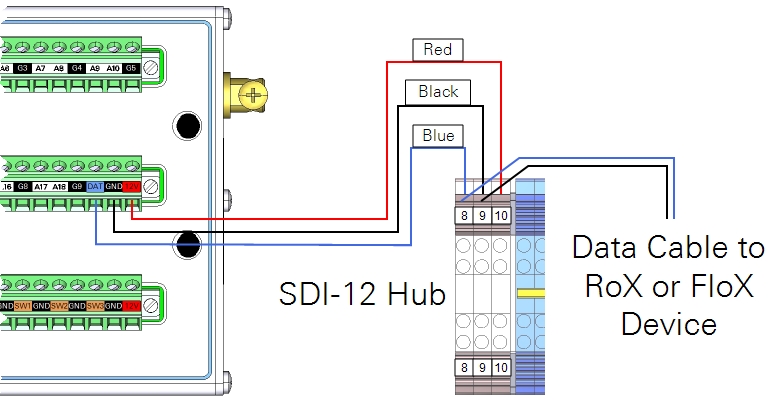
- RoX or FloX SDI-12 cable connection to the DAqM’s SDI-12 port.
- Connect the SDI-12 cable wires to the DAqM’s SDI-12 input. Blue is data, black is ground. Note that the RoX/FloX does not require the SDI-12 power wire to be connected. The RoX/FloX units must be powered separately.
| Color (RoX/FloX) | Description | DAqM | DIN Terminal |
|---|---|---|---|
| Blue | Signal | SDI-12 Signal | 8 |
| Black | Ground | SDI-12 Ground | 9 |
| Not Applicable | Power | Not used |
- |
- Configure the SDI-12 address of a RoX/FloX unit.
- The RoX/FloX has the SDI-12 address 5. If address 5 is already occupied by another SDI-12 sensor, or if the address should be changed for another reason, use the Blueprint Utility, and click SDI-12 Console. Enter the command 5A1 and click Send, which will change the address from 5 to 1. You can use another number for the address.
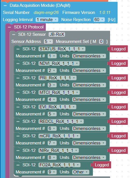
3 | Configuring the DAqM
Below is a Blueprint configuration to read the SDI-12 output at sensor address 5, mapping the output as described in Table 3. The measurement cycle of a RoX/FloX instrument is <1 minute. Data are saved in the EC system’s biomet file, typically at a 1-minute interval.
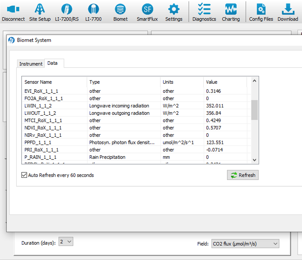
Connect via the Windows interface software to the EC System, open the Biomet window, and verify that the RoX or FloX variables are displayed in the Data tab.
4 | Installation
The receptor of the upward looking fiber (downwelling radiance) has a field of view (FOV) of 180°. Installation on top of the tower is preferable, avoiding shadowing effects by nearby obstacles on the downwelling radiance. Dust and bird protection are optionally available.
The downward looking fiber (upwelling radiance, receptor FOV 25°) should be installed above the area of interest, representative for the eddy covariance footprint. A vertical installation is preferred, deviations of 10° to 15° from the vertical are tolerable.
The higher the downward looking fiber is located above the canopy, the larger the footprint of the upwelling radiance, the more representative is the measurement. The higher the heterogeneity of the canopy, the larger the distance to the canopy should be considered. Table 2 provides recommendations on minimum distances to different vegetation canopies as well as an approximated size of the expected footprint diameter of the upwelling radiance.
5 | RoX and FloX outputs
Both, the RoX and FloX, provide in the standard configuration the same fixed set of variables via their SDI-12 interface, as described in Table 3. Adaptions to the provided variable set might be available upon request to JB Hyperspectral Devices.
For SIF measurements, O2 absorption in the air column between the canopy and the receptor for upwelling radiance may influence the SIF measurement. Correction for compensating the SIF signal loss is preferable to be applied, see also https://doi.org/10.3390/rs10101551. To minimize this effect, consider keeping the distance between the canopy and the downward looking fiber small, preferable < 10 meters.
6 | Notes and troubleshooting
- During sleep time of the RoX/FloX instrument, no SDI-12 data is available.
- SDI-12 variables will be updated after each measurement cycle of the RoX/FloX.
- The SDI-12 cable length was tested up to a 100 meters.
- If the SDI-12 controller retrieves NULL, the following reasons are most likely:
- The SDI-12 connection is not wired properly.
- The datalogger is not configured correctly.
- The RoX/FloX instrument is off or in sleep mode.
- If the SDI-12 controller retrieves “0” in all data fields the reasons are most likely:
- A measurement cycle was not yet performed, wait a moment.
- Serial Transfer of the RoX/FloX is deactivated (set to ON in the config.txt).