Humidity and Air Temperature Probe—Vaisala HMP155
| HMP155 Specifications: | |
|---|---|
| Operating Temperature Range: | -40 to +60 °C |
| Operating Humidity Range: | 0 to 100% RH |
| Voltage Output: | 0 to 1 V |
| Average Current Consumption: | <3 mA |
| Operating Voltage: | 7 to 28 VDC |
For more information and complete operating instructions see: www.vaisala.com/HMP155
Installing the HPM155
- Assemble the Humidity and Temperature Probe.
-
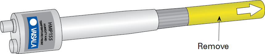
- Remove the protective yellow cap from the sensor prior to use.
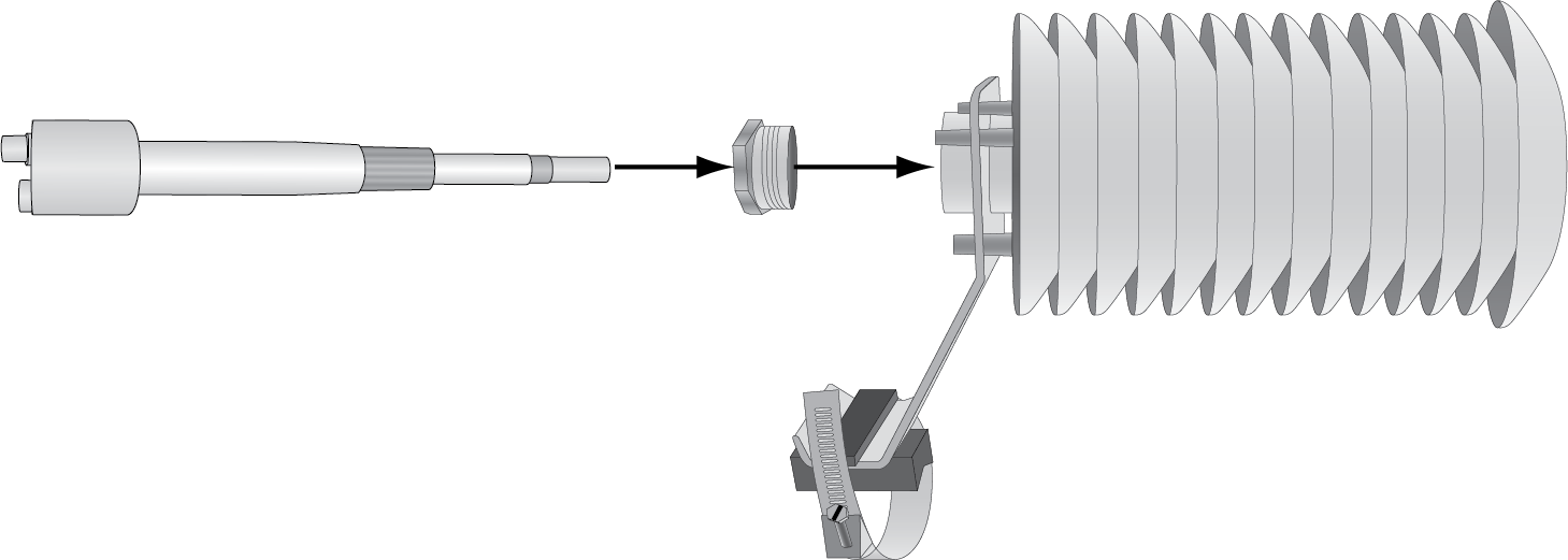
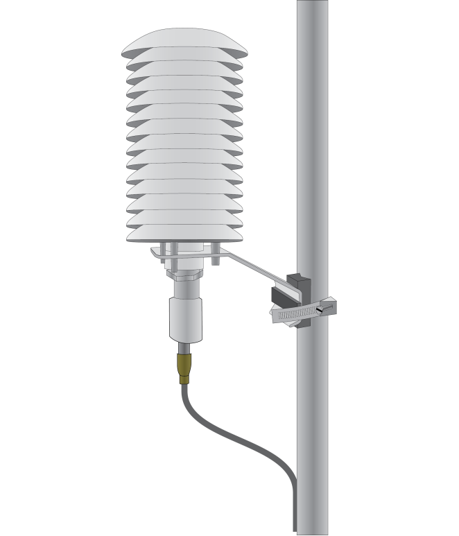
- Install the HMP155 in the R.M. Young 14-plate radiation shield (7900-135).
- Loosen the plastic split-nut on the bottom of the radiation shield and insert the sensor into the split-nut and shield. Tighten the split-nut to clasp the sensor.
- Siting the Humidity and Temperature Probe.
-
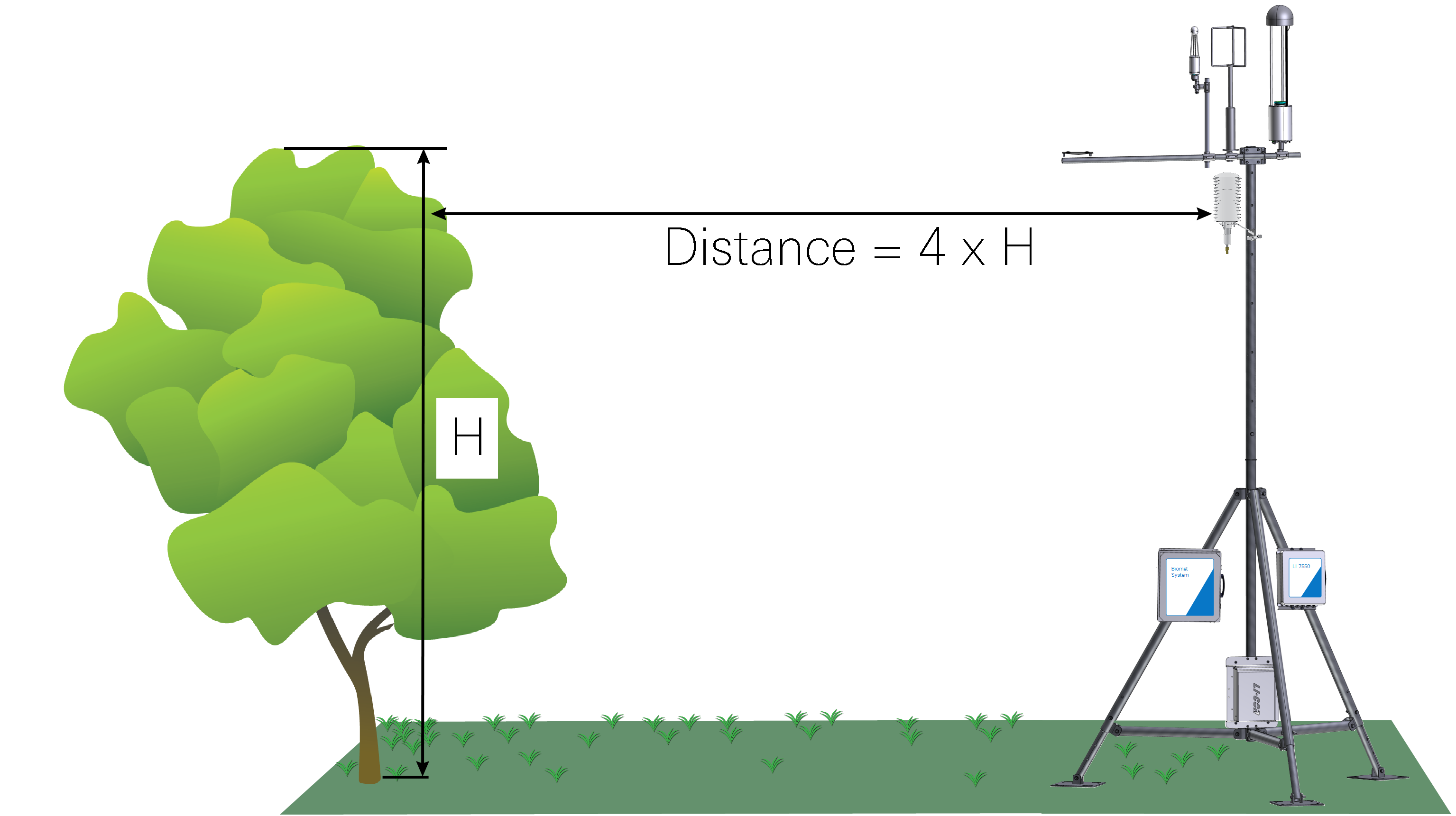
- Place the HMP155 over an open, level area that is free of obstructions.
- Place it at least 30 m from paved areas.
- Position the probe as far above vegetation as possible. If you will use the temperature measurement for eddy covariance data processing, position the sensor close to the sonic anemometer but far enough away that it won't obstruct airflow.
-
 Mount the Humidity and Temperature Probe.
 -
- Wrap the band clamp around a vertical mast.
- Secure the cable to the tower using zip ties. Avoid bending the cable sharply.
- Install the Humidity and Temperature Probe Leads.
- The HMP155 is supported by datalogger programs Biomet_100, Biomet_101, Biomet_102, and Biomet_103.
-
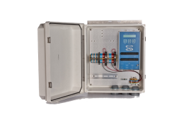
 Note: Route the sensor cable(s) through an opening in the enclosure prior to installing the leads in the terminal strip.
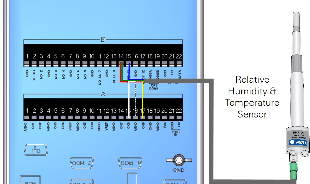
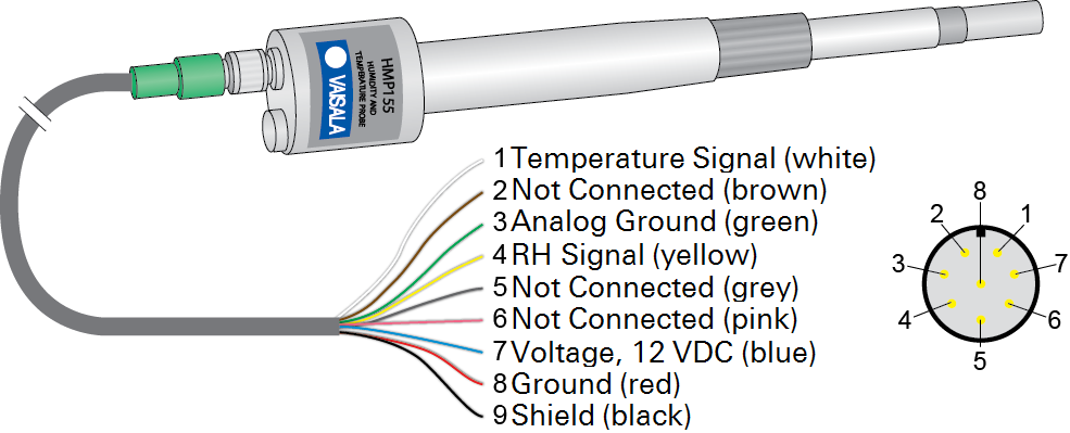
| Description | Color | Terminal |
|---|---|---|
| Temp. Signal (+) | White | A15 (CH8) |
| Shield | Black | A16 (AGND) |
| RH Signal (+) | Yellow | A17 (CH9) |
| Signal Ground | Green | B14 (GND) |
| Power Ground | Red | B14 (GND) |
| Power (+) | Blue | B15 (SW'D12) |
| Not Connected | Brown/Gray/Pink | None |
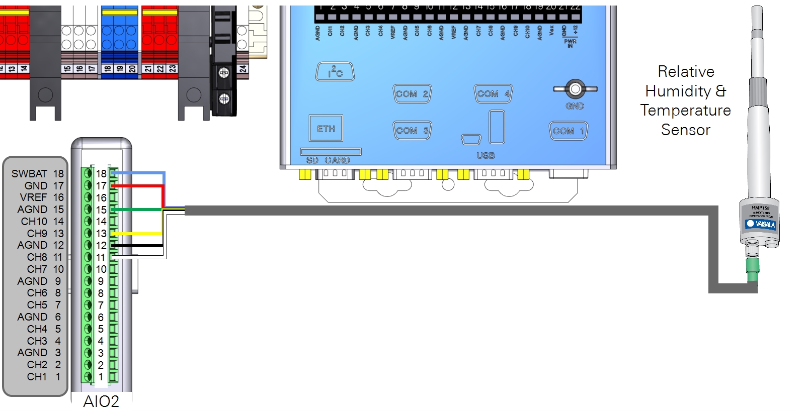
| Description | Color | Terminal |
|---|---|---|
| Temp. Signal (+) | White | 11 (CH8) |
| Shield | Black | 12 (AGND) |
| RH Signal (+) | Yellow | 13 (CH9) |
| Signal Ground | Green | 15 (AGND) |
| Power Ground | Red | 17 (GND) |
| Power (+) | Blue | 18 (SWBAT) |
| Not Connected | Brown/Gray/Pink | None |
Retrieving Data
If the system is configured to log biomet data in .ghg files for processing in EddyPro software or the SmartFlux System, data are stored on the removable USB storage device. Refer to the Biomet Instruction Manual for details.
Maintenance
- Monthly: Check the radiation shield to be sure it is free of debris.
- Check the probe filter for contaminants. Clean or replace as needed. Replacement filters are available from Vaisala.
- Clean the probe with a soft, lint free cloth. Use water and mild detergent if needed.
- In regions near salty bodies of water, salt may accumulate on the radiation shield, sensor, or filter. Salt should be removed by gently rinsing with distilled water.
- Recalibrate the sensor based on the manufacturer’s recommendations.