Net Radiometer—Kipp & Zonen CNR4
| CNR4 Specifications: | |
|---|---|
| Spectral Range (total): | ~300 to 92000 nm |
| Pyranometer: | 300 to 3000 nm |
| Pyrgeometer: | 4500 to 92000 nm |
| Energy Range (upper | lower pyranometer): | 0 to 1000 | 0 to 400 W/m2 |
| Pyrgeometer: | 300 to 500 W/m2 |
| Response Time: | <20 s @ 63% |
| Nominal Sensitivity: | 10 μV/Wm2 |
| Directional Error: | <3% up to 60° |
| Sensor Asymmetry: | <15% |
| Operating Temperature Range: | -30 to +70 °C |
For more information see the manufacturer's instructions at: http://www.kippzonen.com/?product/85182/CNR+4.aspx
Installing the Sensor
- Siting the Net Radiometer.
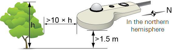
- Install the net radiometer so its view is unobstructed by adjacent structures, trees, and the meteorological station. Select a location that is away from heat sources.
-
- Orient the sensor with the mounting rod pointing toward the north pole in the northern hemisphere or the south pole in the southern hemisphere to minimize shading effects.
- Mount the sensor at least 1.5 m above the plant canopy.
- Mount the Net Radiometer.
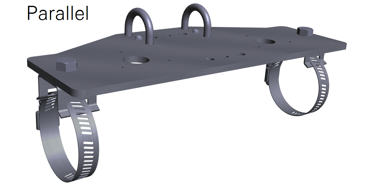
- The CNR4 mounts to the 7900-350 light sensor bracket, which can be affixed to a horizontal cross arm. There are two mounting positions for the net radiometer:
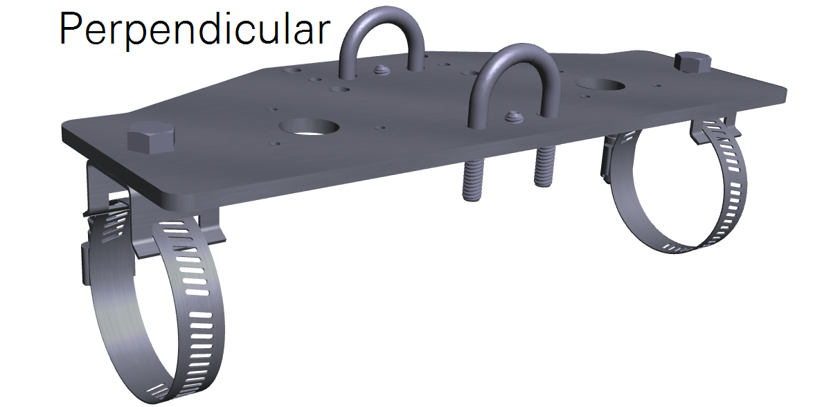
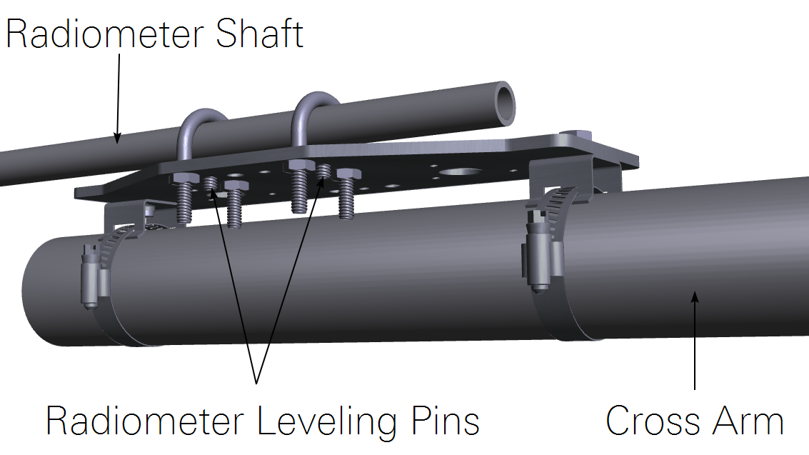
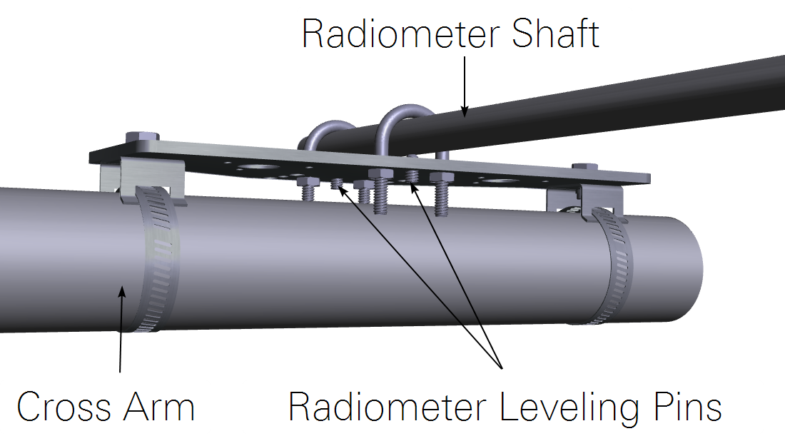
-
- Attach the mounting brackets and band clamps to the plate.
- Tighten the band clamps around the cross arm.
- Attach the U-bolts to secure the radiometer shaft.
- Rotate the radiometer as needed and adjust the leveling pins to level the sensor.
- Tighten nuts to secure the U-bolts.
- Wire the Net Radiometer to the Datalogger.
- The CNR4 is supported by datalogger programs Biomet_101 and Biomet_103.
-
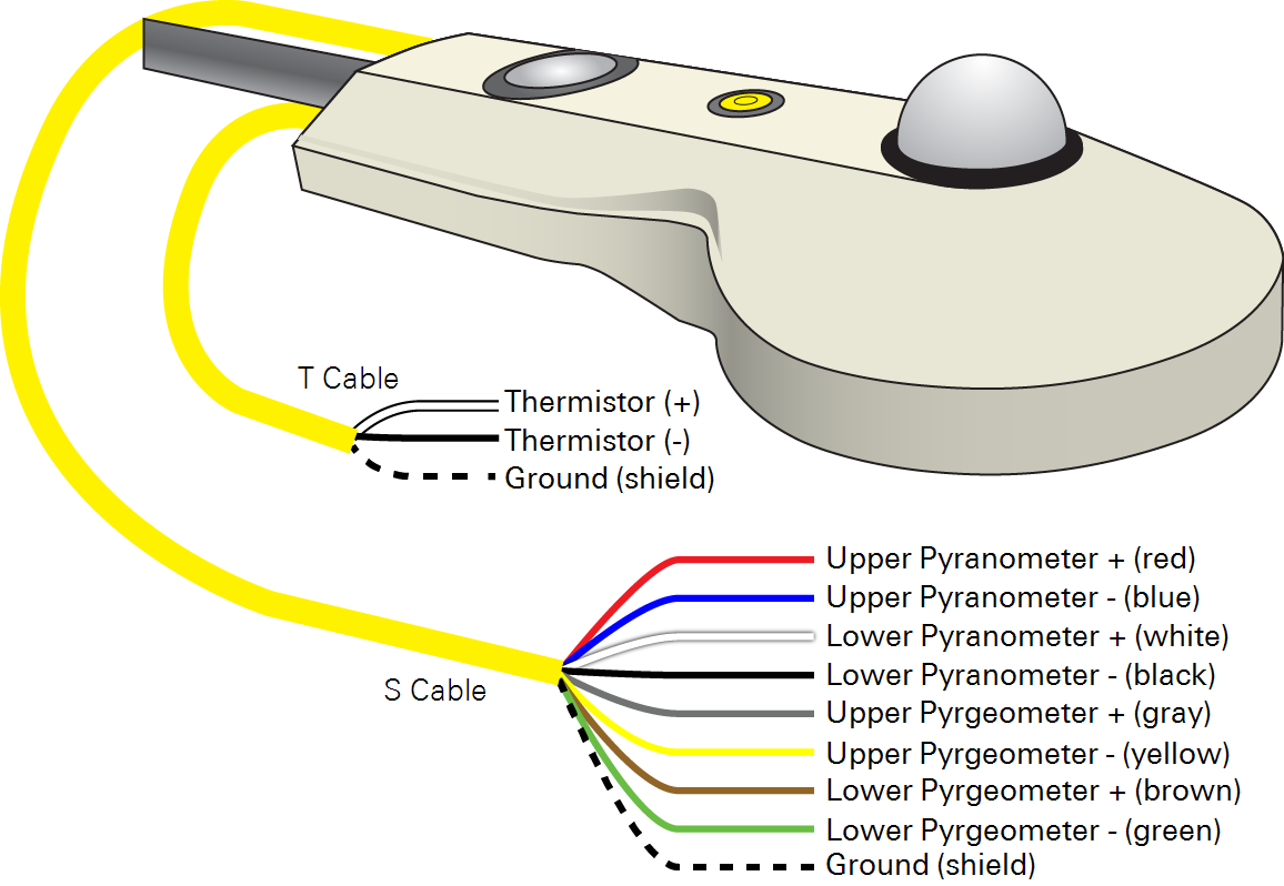
- The radiometer cable (9 leads) connects to the Radiometer S connector.
- The temperature sensor cable (7 leads) connects to the Radiometer T connector.
- Install the 28 Kohm resistor between AIO terminal 13 (CH9) and 16 (VREF).
-
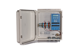
 Note: Route the sensor cable(s) through an opening in the enclosure prior to installing the leads in the terminal strip.
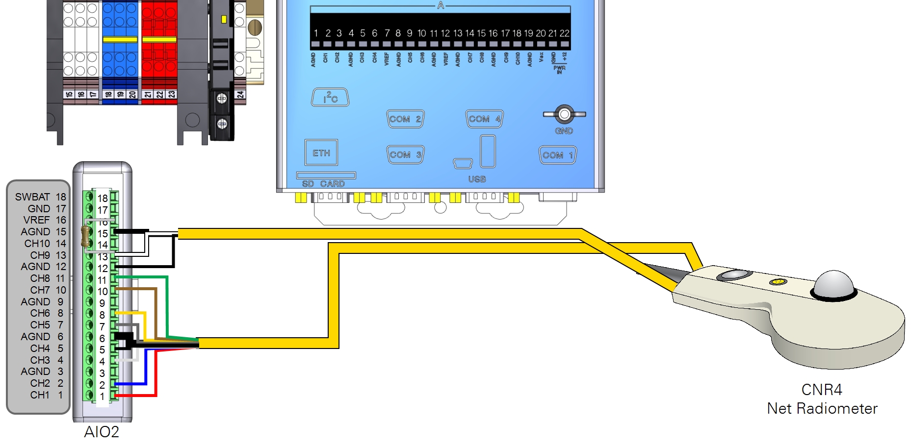
-
Table 2‑4. Radiometer temperature cable connections for Biomet_101 and Biomet_103 programs. Leads connect to AIO2. Radiometer Temperature Cable (T) Description Color AIO2 Terminal Thermistor Black 12 (AGND) Thermistor White 13 (CH9) Shield Black 15 (AGND) 28 Kohm Resistor 
13 (CH9) to 16 (VREF) -
Table 2‑5. Radiometer sensor cable connections for Biomet_101 and Biomet_103 programs. Radiometer Sensor Cable (S) Description Color AIO2 Terminal Upper Pyranometer (+) Red 1 (CH1) Upper Pyranometer (-) Blue 2 (CH2) Lower Pyranometer (+) White 4 (CH3) Lower Pyranometer (-) Black 5 (CH4) Shield Black 6 (AGND) Upper Pyrgeometer (+) Gray 7 (CH5) Upper Pyrgeometer (-) Yellow 8 (CH6) Lower Pyrgeometer (+) Brown 10 (CH7) Lower Pyrgeometer (-) Green 11 (CH8) - Enter the Calibration Constants.
- Follow these steps if you are using programs Biomet_101 or Biomet_103.
- The calibration factors are printed on the cable label. They are also provided on two calibration certificates included with the CNR4 Net Radiometer. First, confirm that the serial number on the sensor corresponds with the serial number on the calibration certificates. One certificate is for the long wave detector, the other is for the short wave detector. Each calibration certificate gives two sensitivity values—one for the upper sensor and one for the lower sensor.
-
Calibration Sheet Label on Calibration Certificate Label in XTerm Software Long Wave Detector SENSITIVITY UPPER SENSOR LONGUPSENS SENSITIVITY LOWER SENSOR LONGDOWNSENS Short Wave Detector SENSITIVITY UPPER SENSOR SHORTUPSENS SENSITIVITY LOWER SENSOR SHORTDOWNSENS - The calibration factors (sensitivity), which are in units of μV/W m-2, should be entered directly into the XTerm datalogger software.
-
- Launch XTerm and connect to the datalogger. In XTerm, click Setup Access and select the Data tab.
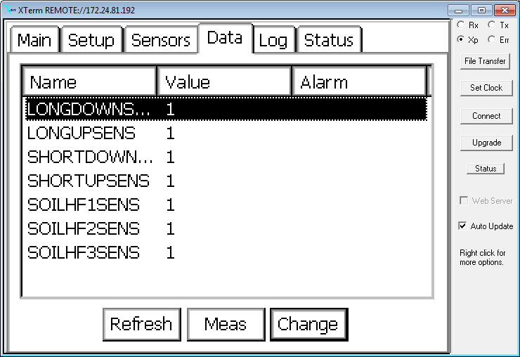
- For the long wavelength sensor on the bottom of the CNR4, select LONGDOWNSENS and click Change.
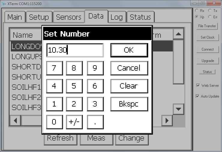
- Enter the sensitivity from the calibration sheet and click OK. In this example, the sensitivity (LONGDOWNSENS) is 10.30 μV/W m-2.
- Repeat this for the other channels of the CNR4, using the appropriate values from the calibration sheets.
Retrieving Data
If the system is configured to log biomet data in .ghg files for processing in EddyPro software or the SmartFlux System, data are stored on the removable USB storage device. Refer to the Biomet Instruction Manual for details.
Maintenance
- Keep domes and windows free of snow, dust, and debris.
- Clean the domes periodically with alcohol or water and mild detergent.
- Check periodically to be sure the instrument is level.
- Replace the drying cartridge every 2 months.
- Recalibrate every 2 years according to the manufacturer's instructions.
Important note about expected values: To correct for the long-wave emissions from the sensor body, a correction based on temperature of the sensor body is incorporated into the long-wave output from the instrument before data are recorded in the datalogger.