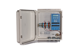
The Sutron 9210B datalogger records biomet data in LI-COR eddy covariance systems. In addition to measuring analog voltage inputs, it can also record data transmitted via the SDI-12 communications protocol from up to ten sensors. Programming a sensor with SDI-12 output requires an extra step—the sensor must be given a unique address. In this example, we connect a Stevens Hydra Probe II soil moisture and temperature sensor to the datalogger.
- Power on the datalogger, and connect to it with the Sutron Xterm software. Make sure that there are no SDI-12 sensors connected to the datalogger yet.
- Click on the Sensors tab. Click on the SDI button on the bottom right.
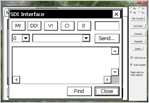
- A new SDI-12 sensor dialog will appear. This is referred to in some documentation as Transparent Mode.
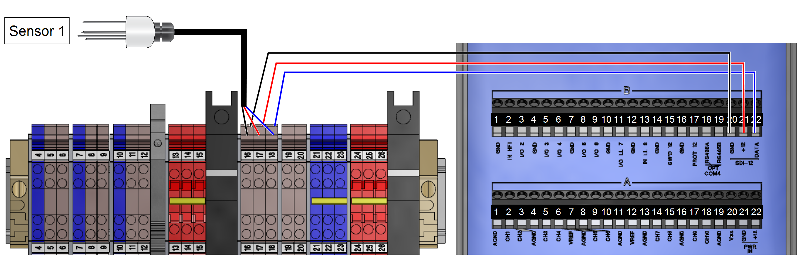
- Connect the signal, ground, and power wires from your first sensor (the one you will designate as Sensor 1) to the proper terminals. If you are using only one SDI-12 sensor, you can connect these wires directly to terminals 20 (ground), 21 (power), and 22 (data) of the B terminal strip on the datalogger. If you are using more than one SDI-12 sensor, connect the wires to DIN terminals 16, 17, and 18 inside the biomet enclosure, and connect wires between these terminals and the datalogger. In the standard biomet packages, for example, three Hydra Probes are connected in this manner.
-
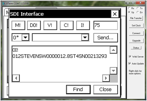
Hydra Probe II; 1, 2, and 3 Color Desc. DIN Terminal Black Ground 16 Red Power 17 Blue SDI-12 Signal 18 Wire Lead Connections Color DIN Terminal Datalogger Terminal 46 cm Black 16 SDI-12 GND (B20) 46 cm Red 17 SDI-12 Power (B21) 46 cm Blue 18 SDI-12 Data (B22) - In the software, click Find. The datalogger will locate the sensor, whose default address is 0.
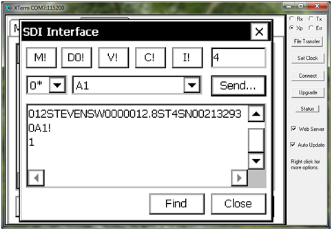
- In the numbered dropdown menu, select sensor 0. Then click Send. A new dialog will open, where you can enter the command A1 to change the sensor’s address to 1. Press OK. The sensor’s address is now changed to 1.
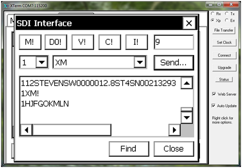
- Now select sensor 1 in the numeric dropdown menu. Click Send. Enter the command XM to query the sensor for its default output. Verify that these are the sensor’s default outputs, based on its documentation. (If this is not displayed, send a new command XM=0.) For the Hydra Probe, for example, these outputs are labeled H, J, F, G, O, K, M, L, and N.
- Repeat steps 4-7 for each sensor. Each time you will need to give the sensor a unique address. Once the sensors are configured, click Close.
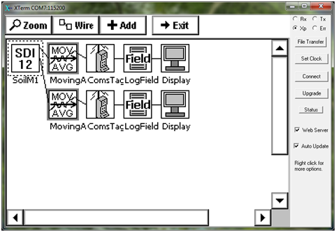
- To program the SDI-12 sensor for measurements, click on the Setup tab and select Graphical Setup. Click Edit. Click Add at the top. Select Input and select the SDI-12 block.
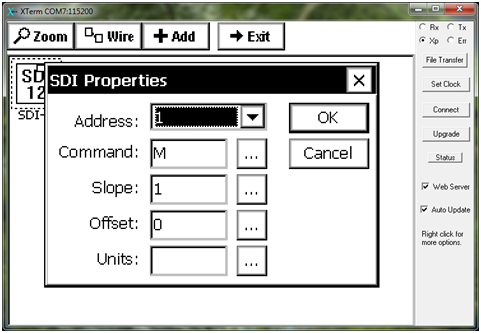
- Click on the newly-added SDI-12 block and select Edit Properties.
- Select the address of the sensor you would like to measure in the numerical dropdown menu. Change the command you will send the sensor. A common command is M, which provides the default outputs of the sensor. Please refer to the sensor manual for information on its particular SDI-12 parameters.
- Add and configure the corresponding blocks for each parameter (a measurement block such as MovingAverage, a LogField block, an optional ComsTag block, and an optional Display block). Add these for each desired parameter—in this example, parameter 1 (first output from command M) is soil moisture, and parameter 3 is soil temperature.