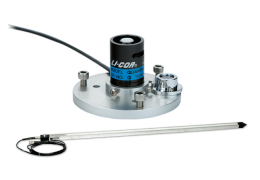
2420 Light Sensor Amplifier
The 2420 Light Sensor Amplifier converts the current (μA) signal from the radiation sensor into a voltage that can be measured by most data loggers and system controllers. The 2420 Amplifier works with both old and new LI-COR radiation sensor designs. Two amplifier models are available:
Note: The 2420 Amplifier is weather resistant with the lid properly attached, but if it is to be left outdoors for long periods of time, it should be installed in a protective enclosure or sheltered location.
2420 Amplifier Gain Settings
The 2420 Amplifier provides 15 discrete gain settings to accommodate a variety of full-scale light intensities, full-scale voltage ranges, and sensor types. This section shows how to determine the correct gain settings and multiplier. Gather the following information:
- Calibration constant for your light sensor (C)
- Maximum full-scale radiation intensity to be measured (Imax)
- Full-scale input voltage of the datalogger or 5.0 V – whichever is lower (Vmax)
Follow these steps to calculate the amplifier gain setting and voltage multiplier:
- Calculate the ideal amplifier gain (Gideal).
-

- Example: Consider a quantum sensor installation with the following parameters:
-
- Sensor calibration constant: C = 6.5 μA per 1000 μmol m–2 s–1
- Full-scale light intensity: Imax = 2000 μmol m–2 s–1
- Datalogger full-scale channel voltage: Vmax = full scale voltage of the logger or 5.0 V (whichever is lower).
-

- Select the gain setting (G) from Table 4‑1 that is less than or equal to the ideal gain from step 1.
- Example: The ideal gain computed in step 1 is Gideal = 0.3846 V μA-1. On the table, the closest actual gain that is less than or equal to this value is G = 0.375 V μA-1.
- Use a number 2 Phillips screwdriver to remove the amplifier lid. Alternate the four screws, pulling the lid up with the screws as you go so that the screws do not bind with the lid.
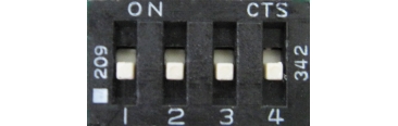
- Using a small screwdriver, set the four switches in the center of the circuit board based on the amplifier gain determined in step 2.
Example: The amplifier gain determined in step 2 (G = 0.375 V μA-1) requires all switches to be in the off position:

|
G = 0.375 all switches off |
|


- Re-install the lid. Torque the screws to 0.45 Nm (64 oz-in.) if using a torque screwdriver.
- Calculate the voltage multiplier (M). The voltage multiplier is used to convert the voltage measured by the data logger into units of radiation (W m–2). The units for M are μmol m–2 s–1 V–1.
-

- Example: Calculate M using G = 0.375 V μA-1 from step 2 and C = 6.5 μA per 1000 μmol m–2 s–1 from step 1:
-

Connecting to a Data Logger
Note: The 2420 Amplifier requires a power supply (white wire, +3.8 to 28 VDC), usually from the datalogger. The datalogger should wait a minimum of 0.12 seconds (120 ms) after providing power before reading the output voltage from the amplifier.
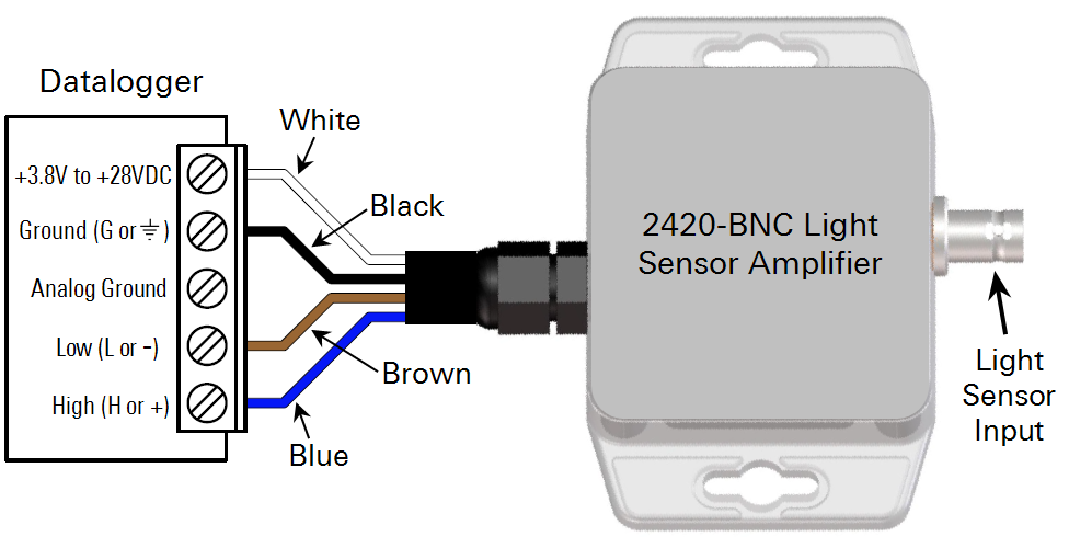
The 2420-BNC and 2420-BL Amplifier output wires (included) can be connected to a datalogger in both differential and single-ended configurations, as shown in the following diagrams. The differential configuration can give better noise rejection and lower offset voltages.
Note: Avoid extending the output wire length. The amplifier and data logger should be kept close together to avoid excess voltage drop and the introduction of noise.
Differential Wiring
Single-ended Wiring
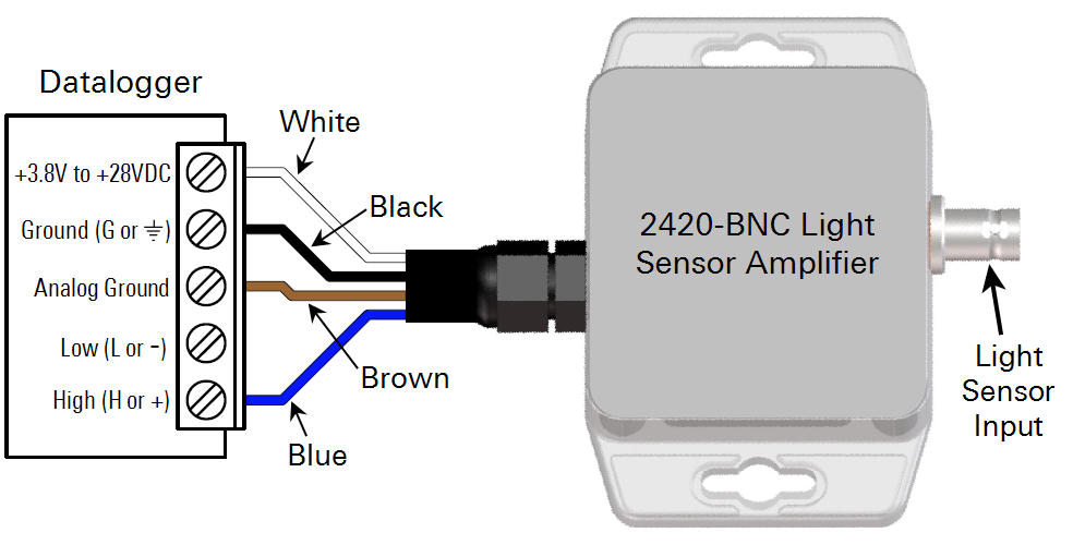
Important Note! In the single-ended configuration, use the following steps to check for ground loops. This procedure only applies when the 2420 is in the single-ended configuration.
- Disconnect the light sensor from the amplifier.
- Using a multiplier of 1 and an offset of 0 in the datalogger program, monitor the "dark offset" mV measurement from the amplifier.
- If the dark offset is > 1 mV, try disconnecting either the brown or black lead (but not both) to minimize the offset.
- If the offset is minimized by removing either the brown or black wire, then move this wire off to the side and insulate it with a piece of electrical tape.
- Reconnect the light sensor to the amplifier and reset the multiplier and offset in the data logger program.
Connecting a Sensor
LI-COR radiation sensors come wired with bare leads or a BNC connector.
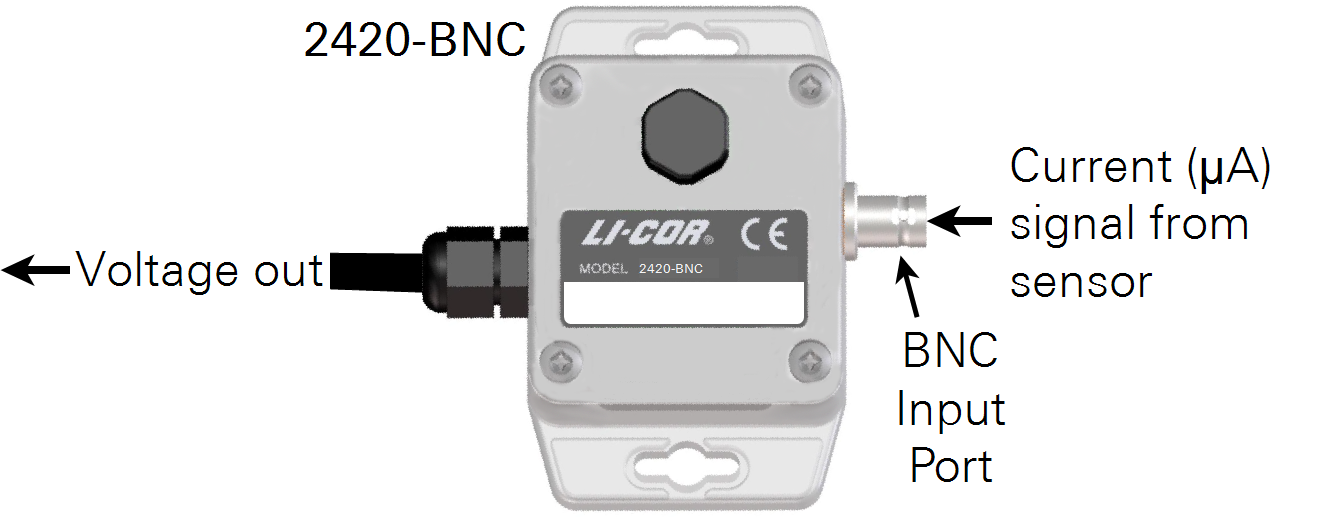
Note: The 2420 Amplifier requires a current (μA) signal from the sensor. It will not work with a millivolt adapter or with a sensor that produces a voltage signal output.
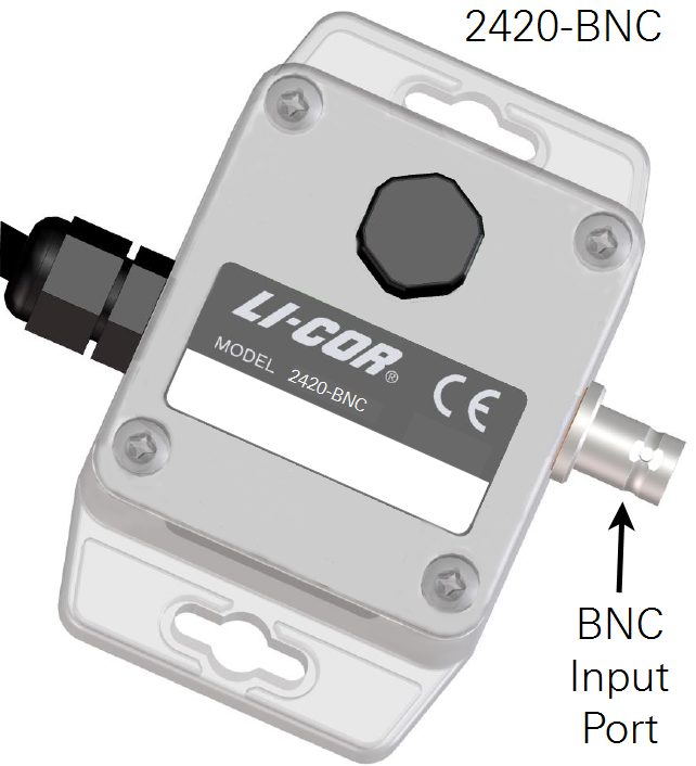
2420-BNC Light Sensor Amplifier: connects to a BNC type light sensor. Attach the BNC connector to the BNC input port on the Amplifier.
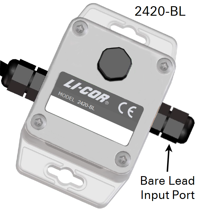
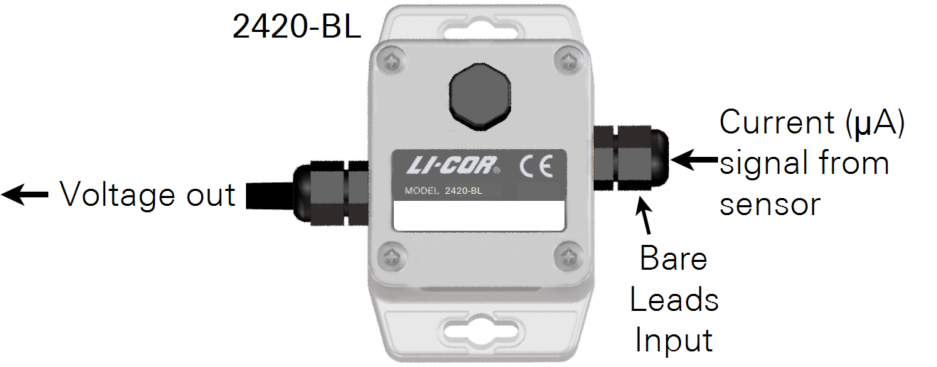
2420-BL Light Sensor Amplifier: connects to a bare lead type sensor with these steps:
- Use a number 2 Phillips screwdriver to remove the amplifier lid. Alternate the four screws, moving the lid up with the screws so that the screws do not bind with the lid.
- Loosen (but do not remove) the black plastic nut on the input port.
- Feed the sensor cable through the nut and input port far enough that the black shielded portion extends inside the amplifier, then hand tighten the nut.
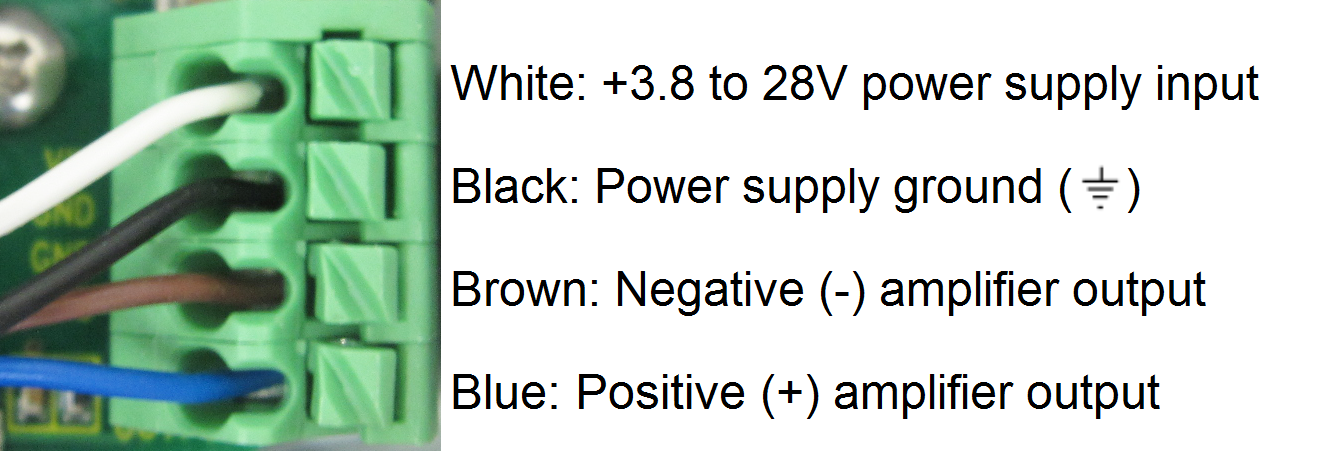
- Press down the connector’s spring release and insert the sensor wires into the terminal block as shown below.

- Re-install the lid. Torque the screws to 0.45 Nm (64 oz-in.) if using a torque screwdriver.
Equation Summary
Output Voltage
The 2420 Light Sensor Amplifier output voltage is computed as:

| Variable | Units | Description |
|---|---|---|
| Vout | V | Amplifier output voltage |
| G | V μA-1 | Amplifier gain setting |
| i | μA | Light sensor photocurrent signal |
Ideal Gain
The ideal gain (Gideal ) is the gain needed by the 2420 Amplifier to adjust the full-scale sensor output to the full-scale input voltage of the data logger. The 2420 Amplifier uses 15 discrete gain settings, so the ideal gain must be rounded down to the nearest supported gain. Ideal gain is computed as:

| Variable | Units | Description |
|---|---|---|
| Gideal | V μA-1 | Ideal amplifier gain |
| Vmax | V | Data logger full-scale input voltage |
| Imax | μmol m-2 s-1 | Quantum sensor full-scale light |
| C | μA per 1000 μmol m-2 s-1 | Quantum sensor calibration coefficient |
Voltage Multiplier
The voltage multiplier M converts the voltage measured by the data logger into a light intensity. The multiplier is found by:

| Variable | Units | Description |
|---|---|---|
| M | μmol m-2 s-1 V-1 | Quantum sensor voltage multiplier |
| G | V μA-1 | Amplifier gain setting |
| C | μA per 1000 μmol m-2 s-1 | Quantum sensor calibration coefficient |
2420 Amplifier Performance Characteristics
The 2420 Amplifier generates an output signal up to 5.0 V and down to -2.5 V over the entire input supply voltage range (+ 3.8 to 28 VDC). The output is linear with the current signal provided by the light sensor with an offset of ± < 10 μV, meaning that 0 μA of input current yields a 0 V ± < 10 μV output voltage.
Note: The 2420 Amplifier is capable of driving a resistive load of 10 kΩ or greater. Most datalogger voltage inputs have an input impedance (resistance) much higher than 10 kΩ, satisfying the output loading requirements of the 2420. Loading the output with a resistance less than 10 kΩ may cause erroneous readings.
Full specifications for the 2420 Amplifier are given in 2420 Light Sensor Amplifier Specifications.