Using the quantum sensors
The procedures for using the LI-192 and LI-193 are very similar.
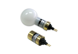
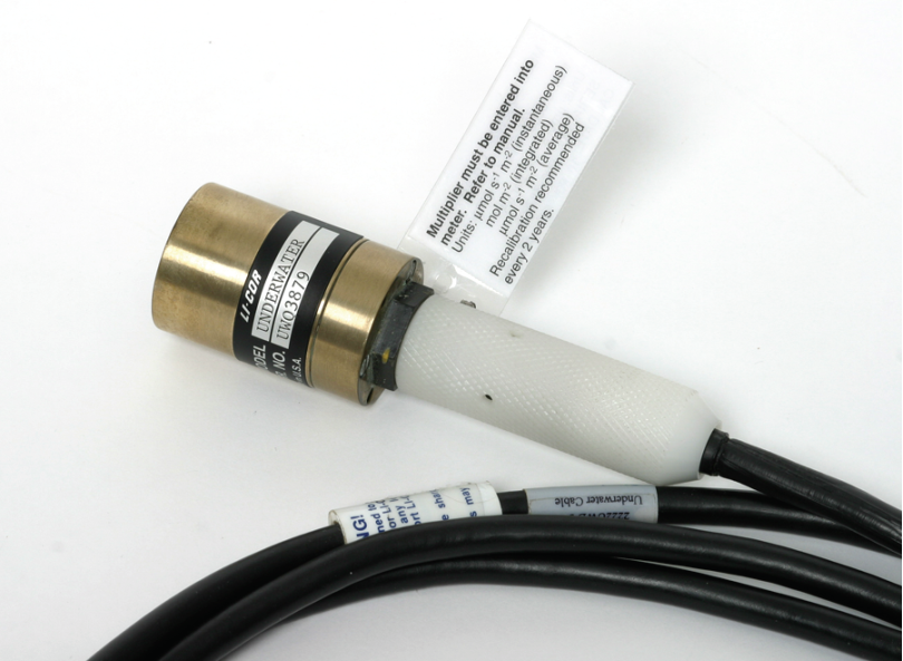
LI-192 Underwater Quantum Sensor
The LI-192 Underwater Quantum Sensor is used for measuring Photosynthetically Active Radiation (PAR) in aquatic environments. With its 400-700 nanometer (nm) quantum response, it is a valuable tool for researching primary productivity or other projects of environmental concern. The sensor can be used in the air with accuracy similar to that of the LI-190 Quantum Sensor. Prior to obtaining atmospheric readings, the sensor must be dried.
New sensor cables from LI-COR are pre-lubricated with a thin film of silicone grease at the factory. The sensor connector may need to be lubricated periodically with a silicone grease (e.g. Dow Corning 111, available from LI-COR under p/n 210-01958-1) before installing it in the mating connector of the underwater cable. The yellow dot on the sensor connector should be aligned with the raised nub on the sensor cable before pushing them together in order to obtain the proper pin connection. If the dots are not aligned, this can result in a negative reading on the readout device due to the change in polarity of the conductors.
Important: Make sure that the underwater cable is inserted fully over the “rib” of the sensor connector before tightening the white collar on the end of the underwater cable. If the cable is not inserted far enough, the sensor leads can be damaged when the collar is threaded over the sensor connector. In addition, the connector pins are small and care should be taken when mating the connectors.
The quantum sensor has three 6-32 tapped holes on the underside of the sensor which are used for mounting the sensor to the 2009S Lowering Frame.
To maintain appropriate cosine correction the vertical edge of the diffuser must be kept clean. Periodically inspect the sensor for foreign deposits on the upper surfaces during prolonged submerged operation.
Immersion effect
A sensor with a diffuser for cosine correction will have an immersion effect when immersed in water. The radiation entering the diffuser scatters in all directions within the diffuser with more of the radiation lost through the water-diffuser interface than in the case where the sensor is in air. This results because the air-diffuser interface offers a greater ratio of the indexes of refraction than the water-diffuser interface. Thus, a greater percentage of radiation entering the diffuser in air reaches the photodiode than in the case where the LI-192 is in water. Therefore, a normal underwater reading would need to be multiplied by this effect if the sensor is used in water.
The LI-192 calibration certificate contains calibration multipliers for both in air and in water operation. The in water multiplier includes the immersion effect correction.
Cosine response
Measurements intended to approximate radiation impinging upon a flat surface (not necessarily level) from all angles of a hemisphere are most accurately obtained with a cosine corrected sensor.
A sensor with a cosine response (follows Lambert's cosine law) allows measurement of flux densities through a plane surface. This allows the sensor to measure flux densities per unit area (m2). A sensor without an accurate cosine correction can give a severe error under diffuse radiation conditions within a plant canopy, at low solar elevation angles, under fluorescent lighting, etc.
The cosine relationship can be thought of in terms of radiant flux lines impinging upon a surface normal to the source (Figure 3‑1) and at an angle of 60° from normal (B in Figure 3‑1). A in Figure 3‑1 shows 6 rays striking the unit area, but at a 60° angle, only 3 rays strike the same unit area (B in Figure 3‑1). This is illustrated mathematically as:
S = (I) (cosine 60°) per unit area
3 = (6) (0.5) per unit area
where S = vertical component of solar radiation; I = solar radiation impinging perpendicular to a surface and cosine 60° = 0.5.

Cosine correction properties
A comparison of the underwater sensor's cosine response curve in air and in water can be found in the "Immersion Effect and Cosine Collecting Properties of LI-COR Underwater Sensors" Report (Application Note #110, available from LI-COR). Engineering requirements result in different correction characteristics for air and water. Over-compensation occurs in air and under-compensation occurs in water. The better response was selected for air, because in water, the direct incident solar radiation does not exceed the critical angle of 48.6° (a result of the air-water interface).
Spectral response
The spectral response is similar to that of the original LI-190 Quantum Sensor (Figure 3‑2).

The spectral response of the quantum sensor is obtained by use of a light source and a monochromator. A sensor which has a known spectral response over the spectral range of interest is used to determine the monochromator output in energy flux density, W(λ), at the wavelength setting . If Q(λ) is the sensor output at wavelength when exposed to the monochromator output, W(λ), then Q(λ) can be approximated by
3‑1Q(λ) = R(λ) W(λ)
where R(λ) is the sensor spectral response at the wavelength setting λ. The above approximation assumes that the monochromator bandwidth, λ, is much less than the wavelength setting λ. The normalized sensor spectral response r(λ), is determined by
3‑2r(λ) = R(λ)/Rm
where Rm is the maximum value of Q(λ)/W(λ) over the range of wavelengths measured.
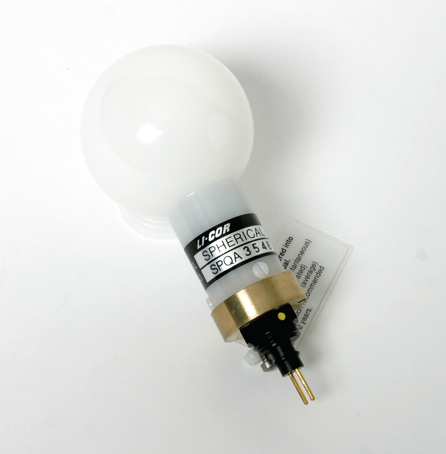
LI-193 Spherical Quantum Sensor
The LI-193 Spherical Quantum Sensor is used for measuring Photosynthetically Active Radiation (PAR) in aquatic environments, and specifically the Photosynthetic Photon Flux Fluence Rate (PPFFR). The LI-193 gives an added dimension to underwater PAR measurements in that it measures PAR from all directions. The LI-193 Sensor can also be used in air.
Because PPFFR can be defined as those photons having a wavelength between 400 and 700 nm that are incident per unit time on the surface of a sphere divided by the cross-sectional area of the sphere, the LI-193 Spherical Quantum Sensor (and all other LI-COR quantum sensors) is designed to respond equally to photons between 400 and 700 nm.
Because the energy of a photon is inversely proportional to its wavelength, a sensor which responds equally to photons will have a linear energy response with wavelength. Therefore, an ideal PPFFR sensor would have a linear energy response between 400 and 700 nm, and would have a slope of 1% per 7 nanometers (nm) if it were normalized to 100% at 700 nm.
Immersion effect
Because of the difference of index of refraction between air and water, the calibration constant of the LI-193 when used in water will be different than the calibration constant when used in air. This phenomenon is known as the immersion effect. The air/water ratio of the calibration constants is equal to the sensor output in air divided by the sensor output in water for the same PPFFR. This ratio is greater than one, and the approximate air/water ratio for normal incident radiation (0°) can be calculated by dividing the "in water" cal constant (listed on the calibration certificate) by the "in air" calconstant.
For an explanation of the immersion effect as well as methods that can be used to determine it, a report entitled "Immersion Effect and Cosine Collecting Properties of LI-COR Underwater Sensors" is available from LI-COR (Application Note #110).
Angular response
The LI-193 sensor uses an acrylic diffuser to obtain an angular response error of less than ± 4% for angles of incidence up to 90° from the normal. Testing is done with a collimated beam of radiation to verify these limits.
Azimuth response
With a collimated beam of radiation at an angle of incidence of 90° from normal, the sensor is rotated about its normal axis. The maximum acceptable variation in response under these conditions is ± 3%.
Spectral response
The spectral response is comparable to that of the LI-190 Quantum Sensor, (Figure 3‑2), as both use computer-tailored filter glasses to closely approximate the ideal linear energy response (flat photon response) from 400 to 700 nm. This response ideally produces an equal output for equal PPFFR even if the spectral irradiance varies within the cutoff points of 400 and 700 nm.
Measurement of the spectral response requires a stabilized light source, monochromator, and calibrated reference detector. Measurements taken with the test sensor and reference detector at many wavelengths yield data points used to plot a relative spectral response. For details, the "Description of Calibration Procedures" application note is available from LI-COR.
Errors
The spatial error of the LI-193 Sensor is due to variations in the diffusing sphere, (negligible), and the sphere area "lost" because of the sensor base. This error is less than -10% for totally diffuse radiation, but is usually smaller than this because the upwelling radiation is smaller than the downwelling radiation.
In highly turbid waters the sensor will indicate high quanta values due to the displacement of water by the sensor sphere volume. This is because the point of measurement is taken to be at the center of the sphere, but the attenuation which would have been provided by the water within the sphere is absent. This error is typically +6.3% for water with an attenuation coefficient of 3 m-1.
Mathematical definitions
The mathematical definition of photon flux fluence rate (PFFR) is
3‑3

where L is the photon flux radiance and Ω is the solid angle. Since d = sinΘdΘdφ, this can be rewritten as
3‑4

The mathematical definition of photon flux density (PFD) as measured by a cosine-corrected sensor is
3‑5

If Θ' = 2Θ then sinΘcosΘ = 1/2 sinΘ' and dΘ = 1/2 dΘ'. Also, the limits of Θ' are 0 to π. Then
3‑6

In a uniform radiance distribution, L(ϕ,Θ) = L(ϕ,Θ') = L (a constant). Then
PFFR = 4πL
PFD = πL
or PFFR = (4)(PFD)
A small spherical collecting surface which exhibits the properties of a cosine collector at every point of its surface would measure the limit of the ratio of total photon flux onto a spherical surface to the area of the surface, as the radius of the sphere tends toward zero. Mathematically, the "photon flux I(Θ,ϕ) per unit solid angle" in the direction (Θ,ϕ) that is intercepted by a spherical surface using the cosine law is
3‑7

where ψ is the angle between the normal of dA and the direction (Θ,ϕ).
Now,  , where r is the radius of the hemisphere (hemi).
Therefore, the total photon flux (F) intercepted by the sphere is
3‑8

This spherical collecting surface would then measure
3‑9

that is, PFFR = 4 times the associated quantity measured by a small spherical collecting surface which exhibits the properties of a cosine collector at every point of its surface in a uniform radiance distribution.
From this fact and also the fact that the cross-sectional area of a sphere = 1/4 the surface area, one could define PFFR as the limit of the ratio of total photon flux onto a spherical surface to the cross-sectional area.
In a uniform collimated beam of radiation, the following conditions of photon flux radiance hold
3‑10

3‑11

where Θ* is small such that sinΘ ≅ Θ and cosΘ ≅ 1.
Then
3‑12


Also,
3‑13


Therefore, PFFR ≅ PFD.
Photon flux fluence rate = photon flux density in a uniform collimated beam if the beam is normal to the cosine collector. One might also note that if the beam is perfectly collimated (Θ* = 0), then the radiance L must be infinite in order for flux to be transmitted.
One could use an alternate approach. The total flux (does not need to be collimated) impinging onto a sphere is
3‑14F = πr2 PFFR
where r is the radius of the sphere, and PFFR is the photon flux fluence rate. If the flux is collimated and covers the entire sphere, then the flux density of the beam would be F/πr2, where r2 is the cross-sectional area of that portion of the beam that is intercepted by the sphere, and F is the total flux in the beam that is intercepted by the sphere. If the beam is uniform, then the flux density is F/πr2 everywhere in the beam. If a cosine-corrected collector is put into the beam, it will measure the flux density times the cosine of the angle between the beam and the normal of the collector. If that angle is zero, then the cosine-collector will measure the flux density (F/πr2) even if its cross sectional area is less than πr2. Therefore, the cosine collector will measure the photon flux density to be equal to the photon flux fluence rate measured by the sphere in a uniform collimated beam of radiation.