
Millivolt Adapters
LI-COR radiation sensors produce a current (μA) output signal that can be converted to a voltage through the use of a resistor. LI-COR makes two types of millivolt adapters for use with our BNC-type radiation sensors. Each adapter includes a precision resistor and a BNC connector that mates with the sensor. Bare leads can be connected to a data logger or other device that reads a voltage signal.
The maximum output of LI-COR radiation sensors in typical conditions is relatively small (microamps of current) and converts into a small voltage. To monitor these sensors with expected accuracy, a data logger needs to have the ability to measure in the microvolt range. To increase sensitivity, make sure the voltage range of the channel is set as close as possible to the full-scale range of the sensor. For example, 0 to 25 mV should cover the range of values expected in a natural sunlight environment.
If the data logger does not have the ability to measure microvolt signals or the ability to set channel voltage ranges down to a 0–25 mV level, another option should be considered, such as the 2420 Light Sensor Amplifier.
2220 Millivolt Adapter
An LI-200R Pyranometer with a BNC-type cable can be used with a millivolt recorder or data logger by connecting a model 2220 Millivolt Adapter. Convert the voltage measured by the data logger into radiation units (W m-2) by applying the appropriate multiplier, given on the sensor's certificate of calibration (see Multiplier for use with LI-COR 2220 (147 Ω) Milllivolt Adapter).
The multiplier M for use with a millivolt adapter can also be found by:
3‑1

The 2220 Millivolt Adapter includes a precision resistor with a fixed resistance of 147 Ω, tolerance of ± 0.1%, and a fixed gain of G = 0.147 mV μA-1. The sensor's calibration constant C is found on the certificate of calibration (see Calibration constant). The calculated multiplier will be a negative number (because the shield of the coaxial cable of the sensor carries the positive signal) and is expressed in units of W m-2 mV-1.
Example: Calculate M using G = 0.147 mV μA-1 and C = 93.75 μA per 1000 W m-2
3‑2

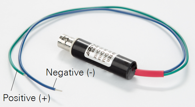
Connecting the 2220 Millivolt Adapter
If the data logger or recorder being used with this millivolt adapter has bipolar capability, connect the positive (green) lead to the common (low) terminal, and connect the negative (blue) lead to signal (high) input. This will help minimize noise.
If the data logger has high, low, and ground terminals, place a jumper wire between the common (low) and ground terminals.
If bipolar signal capability is not available, connect the positive (green) lead to the signal input, and the negative (blue) lead to the common terminal. In this case, use the absolute value of the multiplier.
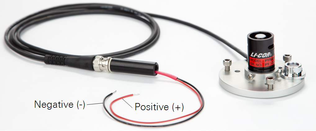
LI-200R-SMV Pyranometer
The LI-200R-SMV Pyranometer includes a Standard Output Millivolt Adapter (part number 2320) terminating in bare leads. The serial number on the pyranometer head must match the serial number on the adapter because the resistance is adjusted to each sensor's current output. This allows a standardized output of 10 mV per 1000 W m-2. The multiplier used to convert the voltage measured by the data logger into a light intensity is -100.0 W m-2 mV-1 (also listed on the sensor's certificate of calibration).
The advantage of using an LI-200R-SMV (compared to an LI-200R-BNC with a 2220 Millivolt Adapter) is that sensors can be exchanged in the field without the need to enter a unique multiplier in the data logger or recorder.
An LI-200R Pyranometer with a BNC-type connector can be converted to an LI-200R-SMV by attaching a Standard Output Millivolt Adapter (part number 2320) to the BNC connector. The 2320 adapter must be matched to the individual sensor. LI-COR needs the sensor's serial number in order to adjust an adapter to match the sensor.
Connecting the LI-200R-SMV Pyranometer
If your data logger or recorder has bipolar signal capability, connect the positive (red) lead to the common (low) terminal, and connect the negative (black) lead to signal (high) input. This will help minimize noise in the signal.
If the data logger has high, low, and ground terminals, place a jumper wire between the common (low) and ground terminals.
If bipolar signal capability is not available, connect the positive (red) lead to the signal input, and the negative (black) lead to the common terminal. In this case, use the absolute value of the multiplier.