Maintenance and calibration
Important: Battery replacement, described on Battery replacement, should be performed only by qualified Service personnel.
Cleaning the LED and photodiode windows
As debris collects on the scanning head windows (insects, dirt, pollen, etc.), spurious numbers will accumulate on the display when the length encoding cord is drawn. This is detected by moving the cord when no sample object is located in the scanning head. Clean the quartz windows with a moist paper towel or cloth. A cotton swab is useful for cleaning the corners at each end of the windows. Wiping the windows with a finger is usually adequate for field use.
Cleaning the length encoding cord guide
A dust trap is located within the length encoding cord guide (the plastic grommet through which the cord passes). This trap reduces dust passage into the scanning head as the cord is retracted. The cord guide should be unscrewed from the upper scanning head section and the felt trap cleaned or replaced. Do not overtighten the cord guide when reinstalling. The service frequency should be determined by experience under the most prevalent usage conditions. The interval will range from seldom under laboratory conditions, to daily in dusty or heavily pollinating crops.
Length encoding cord
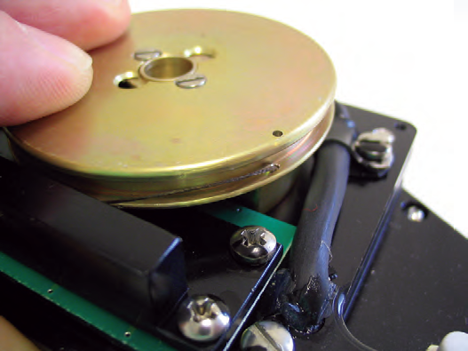
If the length encoding cord becomes lodged, the problem is likely backlash. This seldom occurs even if the cord is released and allowed to retract rapidly. If the operator tends to "push" the cord into the head more rapidly than the system will retract, then a slack cord occurs and backlash is more probable. This is corrected by loosening the cord guide and removing the seven screws on top of the scanning head. The upper housing is then raised straight upward. The cord is rewound and threaded according to Figure 6‑1. When the upper housing is replaced, do not use force. If the cord is broken, see instructions below at ‘Replacing the Length Encoding Cord’.
Caution: When replacing the upper housing, do not allow contact with the protruding edge of the LED scanner. High temperature vacuum grease is used as a seal between the upper housing and the base plate. The grease is forced into the joint after the cover is attached.
Knob separation from the length encoding cord
The length encoding cord will retract completely into the scanning head if the knob is removed. The cord is retrieved by opening the upper housing. Thread the cord back through the knob and tie a number of knots on top of each other to secure the knob. Avoid continuous application of sharp angles at either end of the scanning head cord.
Replacing the length encoding cord
In rare instances the length encoding cord may need to be replaced if it becomes damaged or broken. There is a 4 ft. (1.22 m) length of cord in the spares kit (p/n 214-17616) that is used for replacement. This type of cord is specific for use with the LI-3000C; cords of other compositions will not work in the scanning head. If you need extra replacement cord, please contact LI-COR. The procedure for replacing the length encoding cord is given below. Note that this procedure can be a bit difficult; if possible, we recommend returning the sensor head to the factory for repair. Follow these steps to replace the length encoding cord:
- Remove the 7 screws on the scanning head top lid with a small flat head screwdriver. Lift the top lid off.
- Thread one end of the new length encoding cord through the black knob. Tie a number of knots on top of each other and pull on the cord until the knots lie in the recessed area of the knob and don’t protrude outside of the knob.
- NOTE: It can be difficult to thread the cord through the knob; it may help to thread the cord through a common sewing needle first, and then thread the needle through the knob.
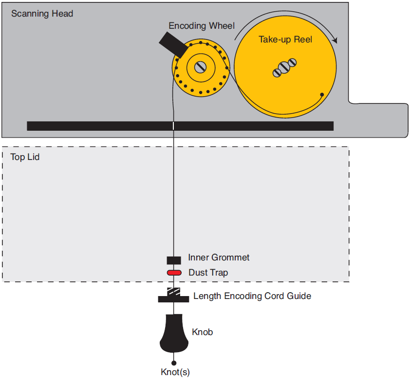
- Figure 6‑2. Length encoding cord insertion into LI-3000C scanning head.
- Unscrew the length encoding cord guide (the black plastic grommet) from the outer side of the scanning head top lid. Thread the free end of the cord through the cord guide, and then through the hole in the side of the scanning head top lid.
- There is another small round plastic grommet on the inside of the scanning head, opposite the length encoding cord guide. Thread this grommet over the free end of the length encoding cord, on the inside of the top lid. The red fiber dust trap is split, and will be put over the cord at the end of this procedure.
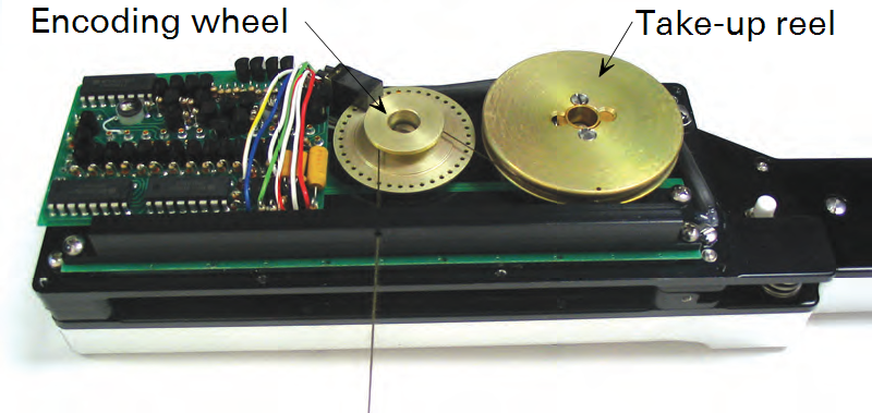
- Thread the free end of the cord through the hole in the black bar on the inside of the scanning head, as shown in Figure 6‑2. Note that Figure 6‑2 shows the final path of the length encoding cord; the cord is not wrapped around the encoding wheel or take-up reel until a later step.
- Note that there is a small hole on the upper edge of the take-up reel. There is a corresponding hole below it, on the inner lip of the take-up reel. The free end of the length encoding cord is inserted through the lower hole; insert the cord from the top of this hole and tie it off with a knot (see Figure 6‑3).
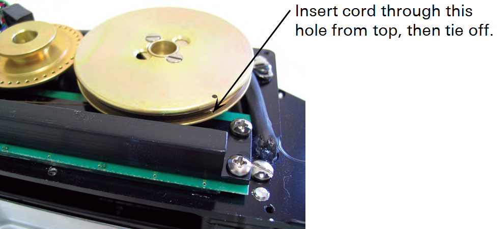
- Figure 6‑3. Insert the cord through the lower hole in the take-up reel, from the top down, and tie off.
- There is a flat metal spring coil under the take-up reel that provides the tension to take up the length encoding cord automatically. This spring can be irreversibly damaged if the take-up reel is turned in the wrong direction. The take-up reel is turned clockwise (without wrapping the length encoding cord around it) until the spring is tight; after the spring is fully tightened, it will automatically wind the cord around the take-up reel.
- Use one hand to turn the take-up reel clockwise – you will need to keep pressure on the top of the wheel while you wind it, to prevent the spring from uncoiling. Hold the slack length encoding cord in your other hand while you wind the take-up reel, and keep it from winding around the reel.
- Figure 6‑4. Turn the take-up reel clockwise with one hand, keeping pressure on it to prevent the inner spring from uncoiling.
- Keep winding the take-up reel until you feel the spring tighten and resist any further turning. Don’t overtighten. Now, hold the cord loosely in one hand, and slowly ease the pressure on the take-up reel; it will automatically uncoil and wind the cord around itself as it turns. Guide the cord around the reel as you release pressure on the take-up reel.
- Turn the take-up reel slightly to create a bit of slack in the cord, and pull the cord from the left edge of the take-up reel, over the encoding wheel.
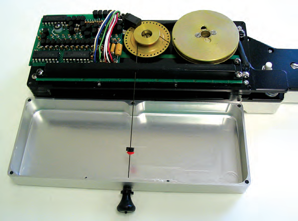
- Figure 6‑5. Take the cord off the take-up reel, and draw it over the encoding wheel.
- Pull on the knob and release a few times to see if the take-up reel is operating properly, and providing the proper tension.
- Slide the red fiber dust trap over the length encoding cord, ahead of the inner grommet, as shown in Figure 6‑2 and Figure 6‑5. There is a small recessed area on the inside of the upper lid; slide the inner grommet and dust trap forward into this recessed area. Turn the lid over and place over the scanning head. Tighten the length encoding cord guide, and replace the 7 screws on the top lid.
Battery replacement
WARNING: Unplug the power cord from the LI-3000C console before replacing the battery. Failure to do so can result in severe electric shock. Battery replacement should be performed only by qualified Service personnel.
As the internal battery ages, the battery life will diminish (12 hours is normal). Eventually the battery will fail to hold a charge and should be replaced. If the battery is faithfully recharged when depleted, it should last a number of years. It is not recommended that a replacement battery be ordered until the battery life of the first battery starts to change noticeably. If a replacement battery is ordered it should be installed immediately to prevent it from deteriorating in storage. Battery replacement instructions are included with the new battery.
Power on problems
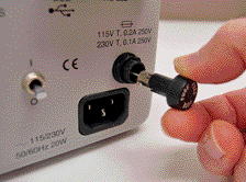
If nothing happens when the LI-3000C is turned on, turn the instrument off, plug in the AC power cord and turn it on again. If the LI-3000C is still unresponsive, check the AC fuse on the outside of the instrument.
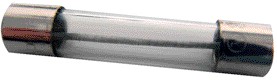
The fuse holder is located on the back panel of the console. Turn the cap counterclockwise to open the holder and inspect the fuse. The fuse is a ¼ x 1 ¼ glass cartridge style; there are spare fuses in the spare parts kit. The 0.2A fuse (p/n 438-08266) is used for 115 VAC; the 0.1A fuse (p/n 438-08267) is used for 230 VAC.
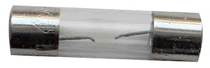
A blown fuse may show scorch marks on the inside glass, and/or a break in the wire element, as shown below left. In some cases, however, a blown fuse may not exhibit any of these symptoms, and can appear to be operational.
|
|
| Blown Fuse | Replacement (good) fuse |
Check the voltage selector switch. If replacing the AC fuse still does not cause the instrument to function properly, turn off the instrument and disconnect the power cord for 3 minutes. Reconnect the power cord and turn the instrument back on. If the battery was deeply discharged, the LO indicator may be displayed for several minutes.
Instrument storage
The internal battery should always be fully charged before storage. For long term storage, charge the battery continuously or at least every 2 months for 5 hours or more. Temperatures between 0 and 35 °C are preferable during charging. Battery life will be severely shortened by long exposure to high temperatures even if charged as recommended.
The LI-3000C should be stored in an area that is within the temperature range - 20 to 55 °C and has a relative humidity of 5 to 95% non-condensing.
Test menu
The TEST key accesses a list of technician test and calibration routines.

These routines are generally used during the technician check-out of the LI-3000C. The list does, however, contain the calibration routine used to calibrate a scanning head to the LI-3000C console.
| Test:keyboard | Tests that all keys are working correctly. |
| Print Cal | Output the calibration to the RS-232 or USB port. |
| Edit Cal | Used to change the calibration data. |
| View Cal | View the calibration data. |
| Calibrate | Sensor head calibration routine. |
| Cal Target | Defines the target brightness for the LEDs. Normal value is 190. |
| Master Reset | Clears all data, time, date, calibration. |
| Test:speedup | Allows checking of string pulling speed. |
| Test:battery | Displays low battery symbol if battery is low, and a high symbol is an overcharging condition is occurring. |
| Test:RS-232 out | Tests the output of the UART. |
| Test:clock | Displays date and time continually. |
| Test:ram | Shows memory size, and does a checksum test. |
| Test:flash | Tests the flash memory. |
| Test:display | Cycles through the character set. |
To exit the TEST menu press any key except ENTER, ↑, or ↓.
Test: keyboard
The message 'keytest' is momentarily displayed, then the display will be blank. When you press a key, the display will show the row number and the column number of the pressed key. The ↑key is 0,0 and the STORE Y key is 3,5.
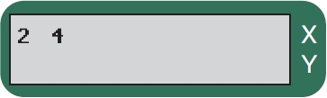
3rd row down, 5th from the right. This is the "6" (or V) key.
To exit this mode, press any key three times, or press all of the keys. If a single key is pressed three times in succession, the display will show ‘THREE TIMES’, and the test will abort.
Print Cal
The Print Cal function outputs the calibration file (via the RS-232 or USB port) to the LI-3000C Application Software. The file is displayed in a Calibration File View window. The file can then be saved from this window.

Press Enter to output the calibration file to the LI-3000C Application Software.
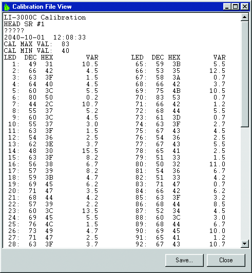
A sample calibration table is shown below. Note that in the example below, LEDs 72 and 73 failed to reach their target values, indicated by ‘FF f’.
| LI-3000C Calibration | ||||||||
| HEAD SR #1611 | ||||||||
| REMARK: XXX XXX XXX 2006-02-14 14:32:02 | ||||||||
| CAL MAX VAL: 91 | ||||||||
| CAL MIN VAL: 52 | ||||||||
| LED DEC HEXVARLED DEC HEXVAR | ||||||||
| 1: | 79 | 4F | 3.7 | 65: | 52 | 34 | 2.2 | |
| 2: | 64 | 40 | 3.5 | 66: | 56 | 38 | 7.2 | |
| 3: | 66 | 42 | 6.2 | 67: | 52 | 34 | 3.5 | |
| 4: | 69 | 45 | 4.0 | 68: | 55 | 37 | 3.2 | |
| 5: | 66 | 42 | 12.5 | 69: | 65 | 41 | 1.2 | |
| 6: | 65 | 41 | 1.7 | 70: | 84 | 54 | 4.5 | |
| 7: | 63 | 3F | 4.7 | 71: | 61 | 3D | 0.5 | |
| 8: | 70 | 46 | 6.7 | 72: | 255 | FF | f | 6553.5 |
| 9: | 67 | 43 | 16.7 | 73: | 255 | FF | f | 6553.5 |
| 10: | 89 | 59 | 9.0 | 74: | 67 | 43 | 6.5 | |
| 11: | 67 | 43 | 5.7 | 75: | 81 | 51 | 2.2 | |
| 12: | 58 | 3A | 2.5 | 76: | 67 | 43 | 10.2 | |
| 13: | 67 | 43 | 2.2 | 77: | 59 | 3B | 2.2 | |
| 14: | 59 | 3B | 1.7 | 78: | 67 | 43 | 7.0 | |
| 15: | 52 | 34 | 2.2 | 79: | 56 | 38 | 1.2 | |
| 16: | 57 | 39 | 2.5 | 80: | 58 | 3A | 4.2 | |
| 17: | 56 | 38 | 6.7 | 81: | 59 | 3B | 3.5 | |
| 18: | 60 | 3C | 8.7 | 82: | 57 | 39 | 1.7 | |
| 19: | 58 | 3A | 5.0 | 83: | 75 | 4B | 2.5 | |
| 20: | 77 | 4D | 2.5 | 84: | 91 | 5B | 2.7 | |
| 21: | 72 | 48 | 18.7 | 85: | 85 | 55 | 4.5 | |
| 22: | 72 | 48 | 8.7 | 86: | 69 | 45 | 11.5 | |
| 23: | 60 | 3C | 1.5 | 87: | 65 | 41 | 6.5 | |
| 24: | 76 | 4C | 1.2 | 88: | 63 | 3F | 6.7 | |
| 25: | 58 | 3A | 9.5 | 89: | 60 | 3C | 5.0 | |
| 26: | 73 | 49 | 5.7 | 90: | 67 | 43 | 1.7 | |
| 27: | 83 | 53 | 13.5 | 91: | 67 | 43 | 3.7 | |
| 28: | 76 | 4C | 14.0 | 92: | 61 | 3D | 6.2 | |
| 29: | 69 | 45 | 2.0 | 93: | 57 | 39 | 13.7 | |
| 30: | 67 | 43 | 0.7 | 94: | 65 | 41 | 2.0 | |
| 31: | 62 | 3E | 5.2 | 95: | 62 | 3E | 3.5 | |
| 32: | 56 | 38 | 8.2 | 96: | 61 | 3D | 7.5 | |
| 33: | 88 | 58 | 2.7 | 97: | 82 | 52 | 4.5 | |
| 34: | 64 | 40 | 8.2 | 98: | 57 | 39 | 6.2 | |
| 35: | 68 | 44 | 0.7 | 99: | 65 | 41 | 1.5 | |
| 36: | 81 | 51 | 3.7 | 100: | 67 | 43 | 3.7 | |
| 37: | 77 | 4D | 8.5 | 101: | 62 | 3E | 3.0 | |
| 38: | 62 | 3E | 0.7 | 102: | 73 | 49 | 13.7 | |
| 39: | 73 | 49 | 3.7 | 103: | 60 | 3C | 0.7 | |
| 40: | 69 | 45 | 8.5 | 104: | 60 | 3C | 7.7 | |
| 41: | 70 | 46 | 3.5 | 105: | 65 | 41 | 14.5 | |
| 42: | 68 | 44 | 0.5 | 106: | 68 | 44 | 6.2 | |
| 43: | 61 | 3D | 3.5 | 107: | 70 | 46 | 5.2 | |
| 44: | 73 | 49 | 3.2 | 108: | 67 | 43 | 3.2 | |
| 45: | 75 | 4B | 5.0 | 109: | 61 | 3D | 5.5 | |
| 46: | 73 | 49 | 3.5 | 110: | 64 | 40 | 11.7 | |
| 47: | 63 | 3F | 6.2 | 111: | 56 | 38 | 2.2 | |
| 48: | 64 | 40 | 5.5 | 112: | 57 | 39 | 1.0 | |
| 49: | 61 | 3D | 22.0 | 113: | 55 | 37 | 16.5 | |
| 50: | 61 | 3D | 3.5 | 114: | 57 | 39 | 8.5 | |
| 51: | 61 | 3D | 6.5 | 115: | 52 | 34 | 3.5 | |
| 52: | 74 | 4A | 6.5 | 116: | 61 | 3D | 5.0 | |
| 53: | 72 | 48 | 5.7 | 117: | 53 | 35 | 4.2 | |
| 54: | 73 | 49 | 0.7 | 118: | 67 | 43 | 12.2 | |
| 55: | 72 | 48 | 1.2 | 119: | 69 | 45 | 3.7 | |
| 56: | 65 | 41 | 0.5 | 120: | 65 | 41 | 10.5 | |
| 57: | 71 | 47 | 1.0 | 121: | 66 | 42 | 9.5 | |
| 58: | 78 | 4E | 2.5 | 122: | 61 | 3D | 12.2 | |
| 59: | 62 | 3E | 0.7 | 123: | 62 | 3E | 3.5 | |
| 60: | 72 | 48 | 0.7 | 124: | 65 | 41 | 16.5 | |
| 61: | 77 | 4D | 4.2 | 125: | 66 | 42 | 6.0 | |
| 62: | 62 | 3E | 4.5 | 126: | 86 | 56 | 1.0 | |
| 63: | 59 | 3B | 1.7 | 127: | 74 | 4A | 12.2 | |
| 64: | 58 | 3A | 4.7 | 128: | 81 | 51 | 4.5 | |
Edit Cal
The Edit Cal routine (technician function only) allows the scanning head calibration data to be changed. Normally the calibration should never need to be manually changed. This routine may be of use in special cases if the head fails the autocalibration routine and the user wants to temporarily get the instrument working. If the instrument fails the autocalibration routine with clean windows, then it does have a problem and should be returned to LI-COR for repair.
The accuracy of the instrument will generally be degraded after the calibration file is edited. This is especially true if the edge of the leaf is near the edited LED. (See Section 1, Theory of Operation. The leaf/no leaf decision will no longer be at 50% for that LED).
The code to access this routine is FP7. After a number is edited, an "e" will appear next to that number in the table. The edited calibration data can only be used until the instrument is turned off. A "CAL FILE LOST" message is displayed if the instrument is turned off and back on, and the autocalibration routine must be used to recalibrate the head.
View Cal
Use ↑and ↓to scroll through the file.
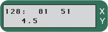
The last LED (128) is set to a value of 81. The entire possible range is 0 to 255, while the acceptable range is from 6 to 249.
The ↑ and ↓ keys will scroll through the 128 calibration values. Press any other key to return to the menu.
Calibrate
The calibration routine must be done if a different scanning head is to be used with the LI-3000C.
Before proceeding with this test, make sure the scanning head is cleaned, and that nothing is blocking any of the LEDs.

Enter the sensor head serial number. Press Enter when done.
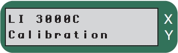
The serial number entered at this prompt is used in the start-up message ("Calibrated for Head #xxxx") given when the LI-3000C is turned on.

Enter any remarks. Press
Enter when done.
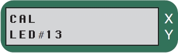
The display will cycle through all 128 LEDs.
The current of each LED is increased until its brightness matches the Cal Target value. Each LED is calibrated 4 times and then averaged.
An error message will be displayed if a problem occurred during calibration. Error messages are discussed below.

The calibration was successful and it passed its performance check.
Error Messages
Acceptable settings for the LEDs are between 6 and 249. If an acceptable value is not achieved, one or more error messages may occur, as shown below. When the calibration is completed, the calibration is saved to FLASH memory, even if one or more LEDs have failed to reach their target value. If an error message occurs, power the LI-3000C off, then back on. Re-check the scanning head to be sure it is cleaned and free of any debris. Then do the calibration routine again. If the error message persists, contact LI-COR.

One or more LEDs failed to achieve the target value.
Make sure the scanning head windows are clean and repeat the Calibrate test.
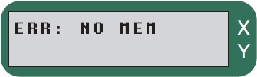
Insufficient FLASH memory to store the calibration. Try deleting some data files to free up memory and retry.
Cal Target
The Cal Target function allows the user to manually set the target value for each LED individually. The normal default value is 190. This is primarily a technician function, and should not be changed.
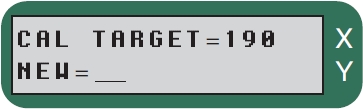
Enter an integer value between 6 and 249.
Master Reset
Clears all data, the time, date, and scanning head calibrations. The instrument is restarted after the Master Reset. Default values for the Cal Target, 3000 Threshold and 3050 Threshold are implemented. A calibration routine must be performed after the Master Reset, as well.
Test: speedup

S (slow) or F (fast).
Tests the speed of the string pull. When the string is being pulled faster than 1/2 meter/second, an F (fast) should appear. When the instrument is in fast mode it may no longer try to update the display. Instead, it may concentrate only on counting area. The data is still reliable, and the newest data are displayed once the string speed slows down. To terminate the test, press any key.
Test: battery
The low battery symbol (lo) will appear if the battery is low, or the high battery symbol (hi) will appear if the battery voltage is too high. Report a high battery condition to LI-COR.

Press any key to return to the menu.
Test: RS-232 Out
This test transmits the character set out the RS-232 and USB ports. A computer must be connected. Press the ← key to abort the test if problems occur. A simple terminal program (e.g. Hyperterminal) can be used to test the RS-232 output by following these steps:
- Connect the LI-3000C to your computer with the RS-232 cable included.
- Open Hyperterminal. On most Windows® machines, Hyperterminal is located in Start>Programs>Accessories>Communications.
- Enter a connection name in Hyperterminal.
- In the ‘Connect Using’ dialog, choose COM1 from the drop-down menu.
- Click OK.
- In the COM1 Properties dialog, set the communications parameters as follows:
- Bits per second (bps): 38400
- Data bits: 8 Parity: None Stop bits: 1
- Flow Control: Hardware
- Click OK.
- When RS-232 OUT is displayed in the Test menu, pressing Enter will cause a character set to be output and captured in Hyperterminal. During this test, the bottom line of the LI-3000C display shows the character(s) being sent. Press any key to return to the menu, or wait until the test ends automatically.
Test: clock
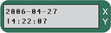
Displays current date and time. Time is displayed using a 24 hour clock.
Press any key to return to the menu.
Test: ram
This routine shows the size of the memory, and gives it a test.

128K bytes memory. Displayed after a few seconds.
If an error occurs during this test, the bottom line of the display will show ‘ERR:AAAAAA, xxxx’, where AAAAAA is the address of the failure, and xxxx is the test pattern. Report this error to LI-COR. Press any key to return to the menu.
Test: flash
This routine does a checksum test on the flash memory.

Flash memory passed the test.
Press any key to return to the menu.
Test: display
The console will automatically cycle through the display's character set. If you want to quit before it finishes, press any key.
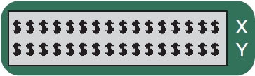
Note that the first symbol displayed is the up arrow key (↑).
Updating the instrument (embedded) software
The LI-3000C internal instrument software is programmed into the instrument’s flash memory; it can be updated using the Update3000C program available from LI-COR’s web site at licor.com/support/home.html. LI-COR may periodically provide updates to the instrument software; follow the instructions below to install the instrument (embedded) software.
Note that the following operation requires only 3-4 minutes to complete. We recommend that you connect the console to AC power before installing the software; if you are using battery power, make sure that you have sufficient charge to operate the LI-3000C for 5 minutes or more. Follow these steps to update the instrument software:
- Turn the LI-3000C off. Make sure the computer and the LI-3000C are connected via the serial cable included.
- There is a hardware jumper inside the LI-3000C console that must be moved temporarily to allow the software update. Remove the 4 screws on the top lid and slide the lid off. There is a set of 3 jumpers stacked at the lower righthand side of the main circuit board, at locations LK5, LK6, and LK8, as shown in Figure 6‑8. Note that the jumper at position LK8 covers only the rightmost pin (out of 2). This jumper needs to be moved over to the left, so that it covers both pins.
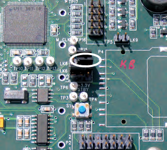
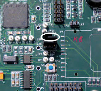
- Figure 6‑8. Move the jumper at location LK8 (left) so it covers both pins (right).
- Move the jumper, and place the lid back on the LI-3000C.
- Locate the Update3000 program, and double-click on the icon to start the program. Alternatively, select Run from the Windows Start menu, and locate the update3000.exe program.
- Choose the serial port on your computer to which the LI-3000C is connected using the arrow keys in the Update Window.
- Turn the LI-3000C on.
- Click the Update Software button. Note that if a connection cannot be established, you may need to reboot the computer.
- The update will begin. A message will appear in the window when the update has been completed, as shown in Figure 6‑9.
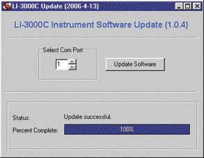
- Figure 6‑9. Click the Update Software button and wait until the Status field displays ‘Update Successful’.
- Wait for the message ‘Update Successful’ to appear.
- Close the Update Window.
- Turn the LI-3000C OFF. Wait 10 seconds, replace the jumper at position LK8 from Step 2 above, and then power the LI-3000C back ON.
- Wait a few seconds for the LI-3000C to initialize. The instrument is now ready to use.