
Connecting the power and data cable
This section describes how to power up the LI-550, connect data cables, configure it, and get data from it.
LI-550F power and data
The LI-550F features a four-wire cable for power and data. The cable can be attached to a data logger or USB adapter.
Power and data wire assignments
Four unterminated wires exit the base of the LI-550F. The wires are color coded to indicate the purpose of each.
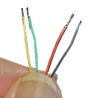
Early models of the TriSonica Mini may have different color wires or additional wires. Refer to instructions accompanying the specially configured sensor for more information.
Connecting the LI-550F to the USB interface adapter
Use a USB-C cable (not included) to connect the adapter to your computer.
Note: The USB adapter is for scientific research and development use only. Do not use the USB adapter in wet locations.
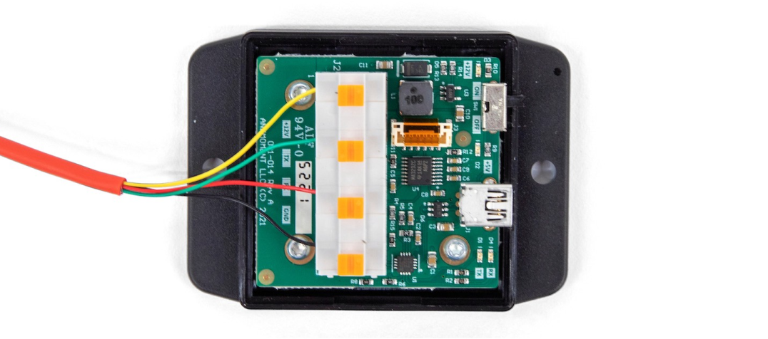
Open the USB adapter case and connect the wires from the LI-550F to the terminal block. Then connect the adapter to a computer using a USB cable.
| Color | Description (LI-550F) | USB adapter connection |
|---|---|---|
| Yellow | Power in; +5 to 30 VDC | 12 V power out |
| Green | RS-232 RX+; serial data receive | TX+; serial data transmit |
| Red | RS-232 TX+; serial data transmit | RX+; serial data receive |
| Black | Ground and serial data return | Ground; data and power |
A video demonstrating this connection is available at licor.com/support/LI-550/videos.html.
LI-550P power and data
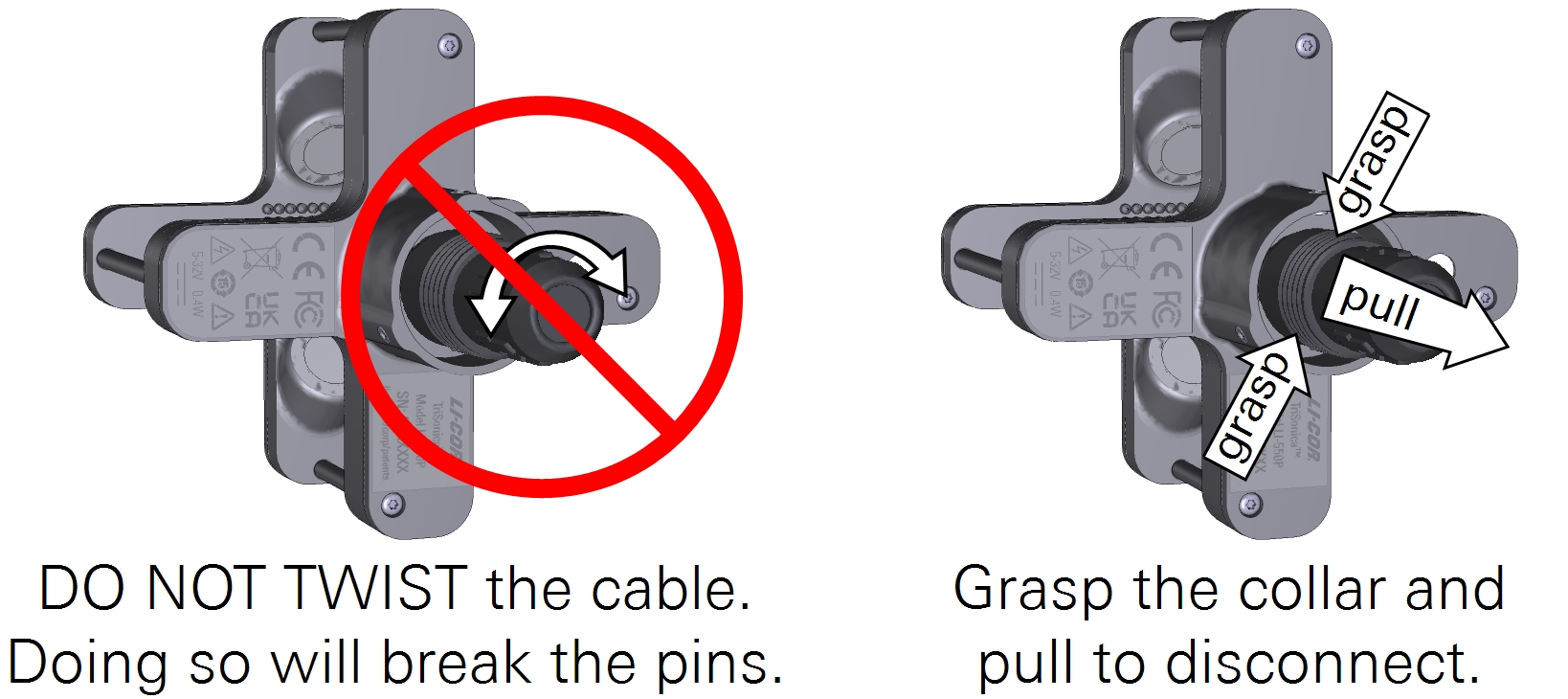
The LI-550P features a 12-pin circular connector. When connected properly, the connector should provide good protection against water ingress. Additional protection can be provided by the mounting configuration.
Important: Do not twist the cable during installation or removal. Doing so will damage the connector pins. To remove the cable, grasp the collar and pull it away from the anemometer.
Pre-made cables with connectors may be purchased from LI-COR in 1.25 and 10 meter lengths. Customized cables and can be made with the custom cable kit. Because this detachable cord carries both data and power, replacement cords or user-built cords must comply with the wiring and insulation specifications set out in the EIA Standard appropriate for the selected communication protocol.
Power and data wire assignments
Figure 3‑2 shows the socket assignments for the connector on the LI-550P. The internal wire colors and descriptions are given in Table 3‑4.
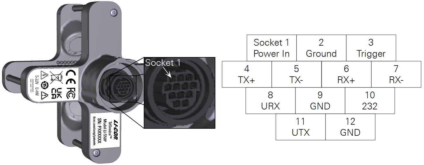
Caution: The Power In wire is the only one that can handle voltages exceeding five volts. Applying excess voltage to other wires can damage the LI-550. Such damage is not covered by the warranty.
Connecting the LI-550P to the USB interface adapter
Note: The USB adapter is for scientific research and development use only. Do not use the USB adapter in wet locations.
The single-terminated blunt-cut cable is to connect the LI-550P to the USB adapter. Separate the brown, blue, yellow, red, and black wires from the bundle and strip 3 mm of insulation from the ends of each wire. Open the adapter case and connect wires to the terminal block as shown in Figure 3‑3.
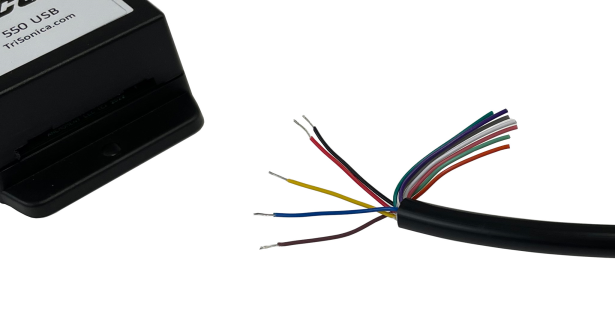
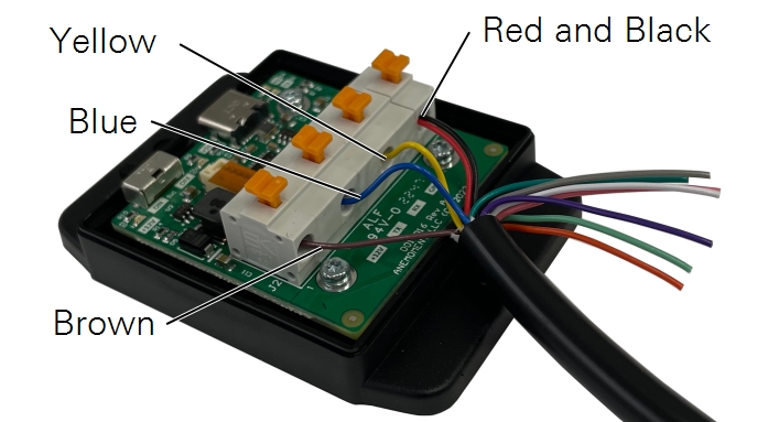
Note: The cable contains 12 wires to accommodate the multi-protocol capable LI-550P. Some wires are not used in this application.
A video demonstrating this connection is available at licor.com/support/LI-550/videos.html.