Connecting the power and data cable
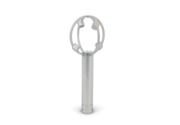
The LI-560 features a 12-pin socket connector as shown in Figure 3‑1.
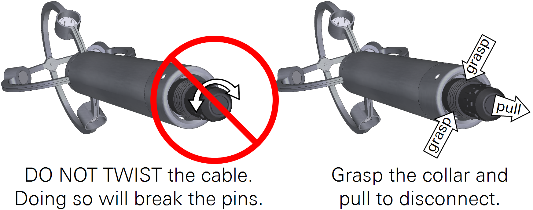
Important: Do not twist the cable during installation or removal. Doing so will damage the connector pins. To remove the cable, grasp the collar and pull it away from the anemometer.
Pre-made cables with connectors may be purchased from LI-COR in 1.25 and 10 meter lengths. Customized cables up to 25 meters in length can be made with the 571D-C custom cable kit. Because this detachable cord carries both data and power, replacement cords or user-built cords must comply with the wiring and insulation specifications set out in the EIA Standard appropriate for the selected communication protocol.
Power and data wire assignments
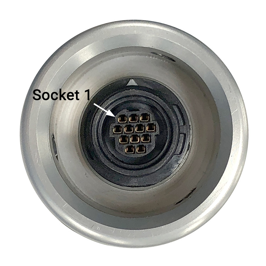
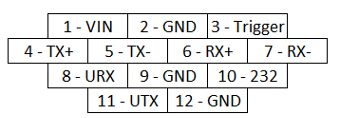
Figure 3‑1 shows the socket assignments for the signal connections and positions within the connector in reference to looking at the bottom of the LI-560. The cable internal wire colors and pin description are given in Table 3‑1.
Caution: The Power In wire is the only one that can handle voltages exceeding five volts. Applying excess voltage to other wires can damage the LI-560. Such damage is not covered by the warranty.
Connecting the LI-560 to the USB interface adapter
Note: The USB adapter is for scientific research and development use only. Do not use the USB adapter in wet locations.
The single-terminated blunt-cut cable is to connect the LI-560 to the USB adapter. Separate the yellow, blue, red, black, and brown wires from the bundle and strip 3 mm of insulation from the ends of each wire.
Open the adapter case and insert the wires into the terminal block holes as shown in Figure 3‑2. The wire colors do not correspond to the color labels, if present.
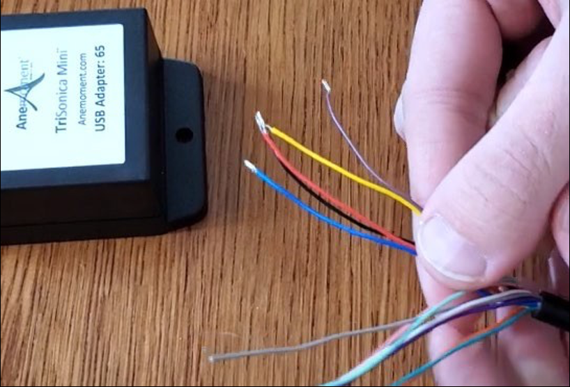
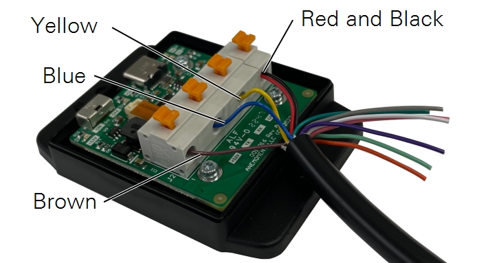
Note: The cable contains 12 wires to accommodate the multi-protocol capable LI-560. Therefore, these color assignments do not match the labels, if present.
A video demonstrating this connection is available at licor.com/support/LI-560/videos.html.