Using the LI-570
The section describes how to install the LI-570 and assemble the cable connectors.
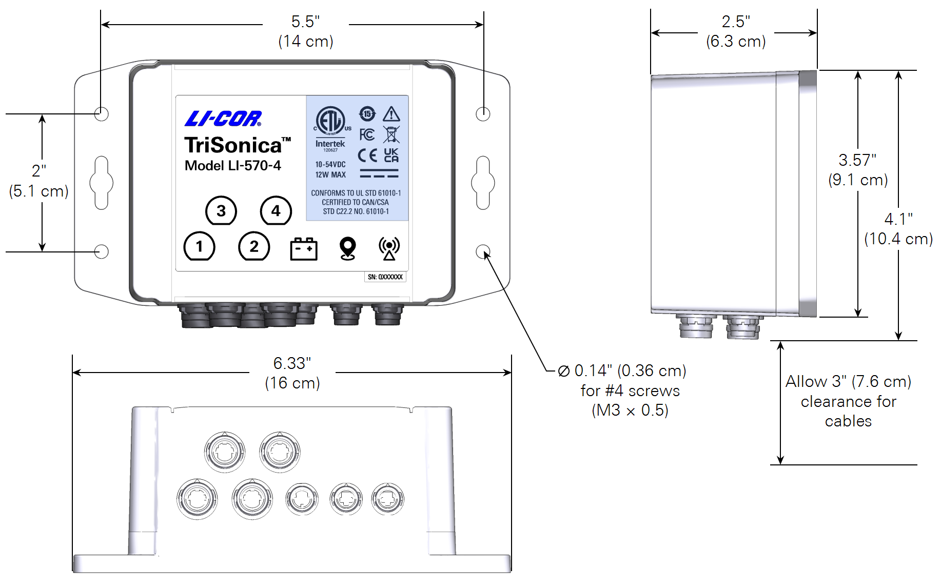
Field installation
The LI-570 features a weather-resistant enclosure with connectors for devices. Install the enclosure with connectors pointing to the ground or to the side, and keep the covers in place on unused connectors to prevent water ingress. When planning your installation, keep in mind that you will need to remove the data logger to access the internal memory card.
Powering the LI-570
The LI-570 receives power through the 3-pin power connector. A 3-socket connector (part number 309-20376) is packaged with the LI-570 unit. Assemble the connector and attach it to a power supply to power on the LI-570.
A suitable power cable will have two 20 AWG (0.5 mm cross-section) wire leads with an outer diameter from 4.2 to 5 mm (required for ingress protection). The wire gauge for the power connector must be large enough to handle the maximum current requirements of the LI-570, connected instruments, GPS receiver, and radio.
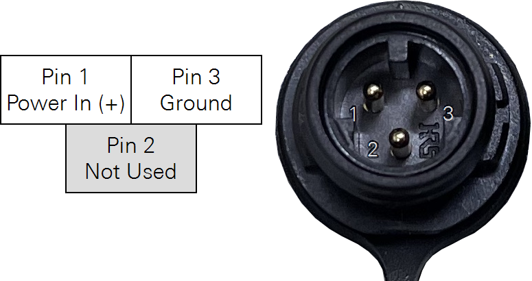
| Pin | Description |
|---|---|
| 1 | Power in (+10 to 54 VDC; 12 watts). |
| 2 | Not connected. |
| 3 | Power ground. |
The LI-570 provides power to the connected instruments, a GPS receiver, and radio. The total power required by the LI-570 is dependent on the number and types of instruments connected.
Connecting devices to the data logger
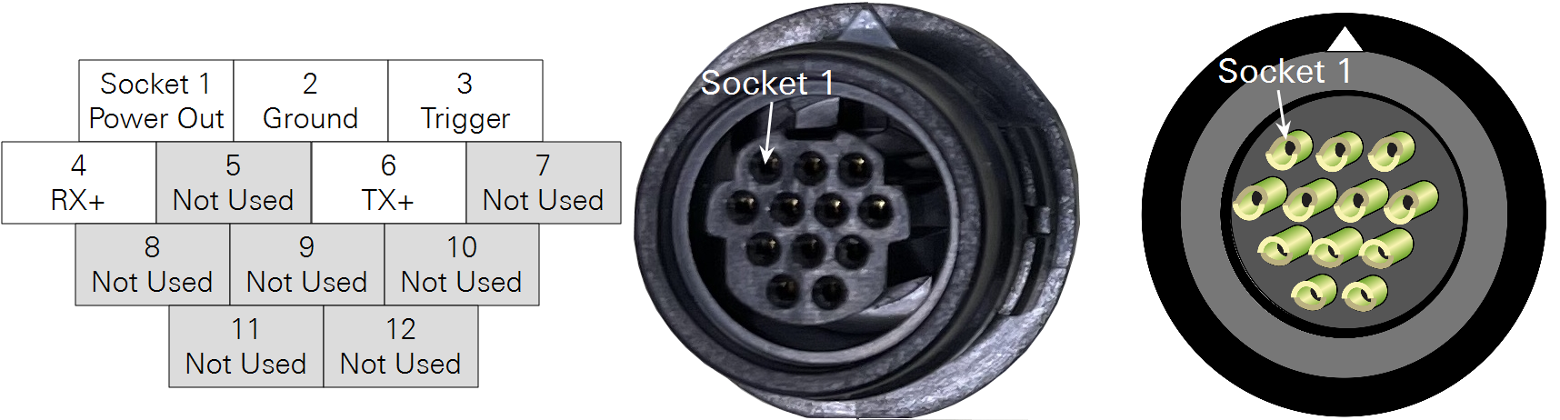
The LI-570 serial input connector uses the same 12-socket connector found at the base of the LI-560 and LI-550P sensors. Figure 2‑3 shows the socket assignments on the connector.
Note: Make sure that each LI-570 external connection port is either connected to a sealed cable or is covered by cap. Do not apply power to the LI-570 in wet conditions if any external connection ports are exposed.
Connecting TriSonica anemometers
Connect the LI-550P and LI-560 anemometers to the data logger using double-terminated cables. The 571D-1, 571D-10, and 571D-C cables are symmetrical - either end can be connected to the LI-570 instrument connector and the LI-550P or LI-560 sensor. Power is supplied by the LI-570.
Connecting other serial instruments
A serial instrument other than a TriSonica anemometer may be connected to the LI-570 by wiring the serial instrument to a 12-pin single-terminated cable with blunt-cut end. Table 2‑2 gives the signal names and wire colors for the 12-pin cable. Assemble the cable connector as described to ensure that the connector is protected from water.
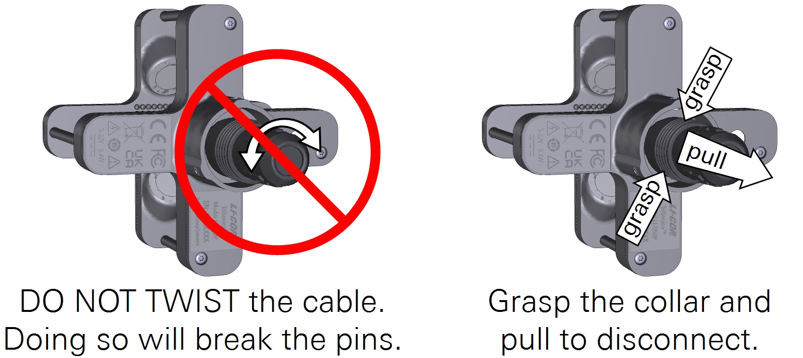
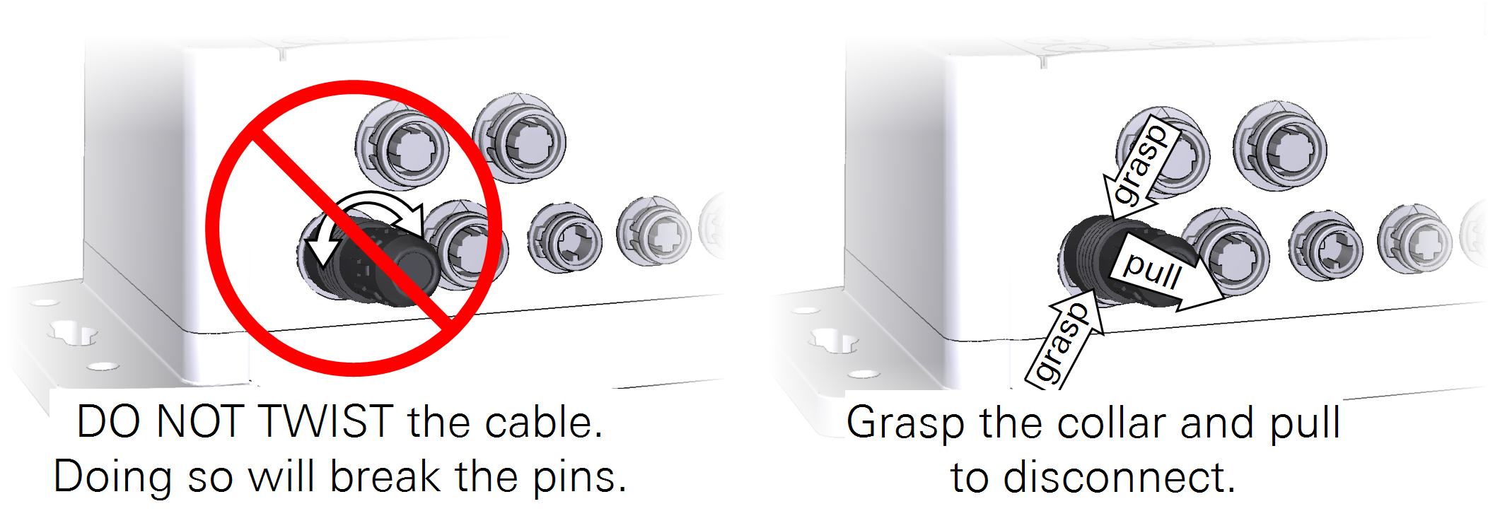
Important: Do not twist the cable during installation or removal. Doing so will damage the connector pins. To remove the cable, grasp the collar and pull it away from the anemometer.
Connecting a GPS receiver or radio transceiver
The LI-570 uses a 6-pin connector for 3.3 V UART serial connections. Two 6-pin connectors (part number 310-20390) are included with the LI-570. These should be attached to a user-supplied cable. A suitable cable will have five 20 AWG (0.5 mm cross-section) wire leads with an outer diameter from 3.5 to 4.3 mm (required for ingress protection).

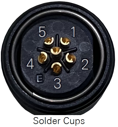
Table 2‑3 gives the assignments. Note that the connector must be joined with a matching connector that is sealed prevent water ingress.
Assembling cable connectors
Connectors are shipped ready for assembly to a user-supplied cable. For most connections, 22 AWG wire (0.33 mm2) will work. The largest compatible wire is 20 AWG (0.52 mm2).
- Trim the cable to the desired length.
- Remove about 10 mm of insulation from the end of the cable and strip 2 mm of insulation off of each wire.

- Twist the strands of each wire just enough to prevent unraveling.
- Assemble the connector components and cable.
- Insert the cable through the shell, strain relief, bushing, spring, and locking collar in the order shown.

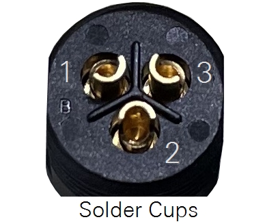
- Solder the wires to contacts.
- For each pin and wire, set the wire in the solder cup and secure it with a small amount of solder.
- Assemble the connector.
- Align the components and slide them together. Tighten the shell snugly over the contact assembly.
- Optional: Check the connections with an ohm meter.
- There should be no resistance across connected pins and infinite resistance across the pins that are not connected.