Leaf angle and GPS
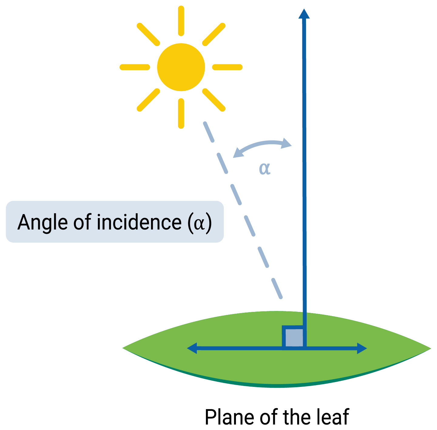
Using measurements from the accelerometer / magnetometer and GPS receiver, the LI-600/LI-600N computer software calculates the leaf angle relative to the sun at a given time and place, which is the angle of incidence.1
Accelerometer/Magnetometer
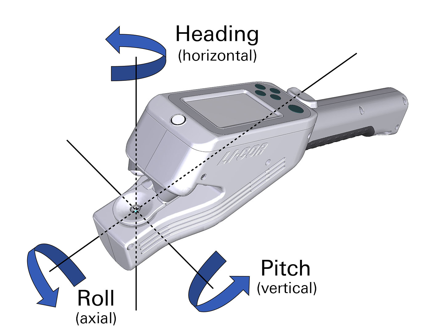
The accelerometer and magnetometer measure three aspects of a leaf's angle:
Pitch: slope from horizontal in degrees (accelerometer)
Roll: rotation from the horizontal in degrees (accelerometer)
Heading: rotation from North in degrees (magnetometer)
GPS
If GPS is enabled in the instrument settings and there are a minimum of 3 satellite signals, a GPS map pin will appear in the upper left of the device screen. To view the number of satellites available, go to Instrument Settings on the device, select GPS, then NumSats.
Note: It can take up to five minutes after powering on the instrument to get a satellite fix. Therefore, if you take measurements before seeing the GPS pin at the top of the instrument display, those measurements will not include GPS/leaf angle data.
Leaf angle software calculations
The LI-600/LI-600N software application combines data from GPS and rotational information to compute parameters related to solar position and leaf angle position relative to the sun. The angle of incidence of a surface (here, a leaf) arbitrarily oriented with respect to the sun at a given time and place can be given by:

where angle_incleaf is the incidence angle between the leaf and direct sunlight (angle_incleaf = 0 for leaf plane perpendicular to direct sunlight). The equation above is Equation 47 from Reda & Andreas 2004. Input parameters are calculated from either GPS location information or accelerometer/magnetometer information as follows below.
The proportion of direct sunlight incident on the leaf at the given angle can also be calculated
9‑50

where directpct is the % of available photons incident on the leaf relative to the amount of photons if the leaf were normal to direct sunlight.
Solar position calculations
Location and time from GPS are used to calculate solar parameters. The solar parameters can be solved using equations from Michalsky 2008. Those equations are valid for the years 1950-2050 with uncertainty of ±0.01°.
Leaf plane calculations
Two parameters are needed to describe the plane of the leaf:
slopeleaf Inclination of a surface from the horizontal position
azleaf Surface azimuth angle or deviation of the normal to the surface with respect to the south
The following equations are similar to those from Escribano-Rocafort et al. 2014, with modifications to fit the LI-600/LI-600N framework.
9‑51

9‑52

Clocks
With the addition of GPS, the LI-600/LI-600N reports two different time stamps in the data file: a date/time stamp in the SYS group, and a date/time stamp in the GPS group. The date/time stamp in the SYS group is either set manually by the user or synced to GPS (when available).
GPS not available
If the user is unable to get enough satellites for GPS, the clock needs to be set manually (Instrument Settings > Set Time > Manual). In this case, the SYS Date/Time will update based on user settings. GPS time will not be available and is logged as time = '0:00:00' and date = '0000-00-00'.
GPS available
When GPS is available, the GPS clock will reflect Universal Time. The user can use the SYNC function to update the SYS clock and set their UTC offset for local time (Instrument Settings > Set Time > GPS Sync).
If SYS is not synced to GPS, the time reported in the SYS group reflects the last manual update, and may not match the GPS clock. The real-time clock for the SYS group will drift over time, typically a few seconds a month, therefore it is good practice to sync with GPS once lock is achieved before taking measurements. In a logged data set, the SYS and GPS times can be compared to determine the UTC offset. UTC offset is maintained through power cycling of the instrument.