610-02 Relative Humidity Calibration Accessories
Printable PDF: 610-02 Relative Humidity Calibration Accessories
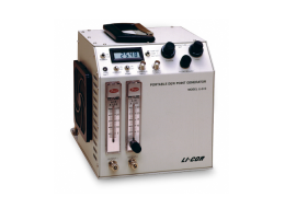
The 610-02 RH Calibration Accessories are designed to be used with the LI-610 Portable Dew Point Generator to facilitate calibration of the relative humidity sensors in the LI-6200 or LI-6000 Portable Photosynthesis Systems, and the LI-1600 Steady State Porometer.
Check to be sure that you have received the following three items:
- Nickel-plated aluminum block - for attaching to the LI-6200 or LI-6000 leaf chamber sensor housing.
- Calibration cap - for attaching to the LI-1600 cuvette.
- 1/16" (1.59 mm) ID teflon tubing - a short section of 1/16" tubing is included for connecting to the small hose barb on the LI-1600 cuvette exit port. Follow these instructions for installing the 610-02 RH Calibration Accessories. Complete calibration procedures are outlined in the LI-610 Instruction Manual.
Installation Instructions
LI-6200 or LI-6000 Portable Photosynthesis System
- Mount the LI-6200 or LI-6000 sensor housing in a vise, if possible. Unhook the leaf temperature thermocouple from the monofilament support lines, and then remove the chamber from the sensor housing. BE VERY CAREFUL NOT TO TOUCH, SCRATCH, OR SMOKE NEAR THE EXPOSED HUMIDITY SENSOR.
- Check to be sure that the sensors and exposed parts of the sensor housing are clean and free of debris.
- Attach the nickel-plated aluminum block to the sensor housing (Figure 1) and tighten it down. Allow the leaf temperature thermocouple to hang free outside the aluminum block. The sensor head O-ring will seal around the thermocouple wires sufficiently well to prevent serious leaks.
- Remove the top plate from the sensor housing by removing the four corner screws to expose the zero and span potentiometers.
- Disconnect the two Bev-a-line hoses from the barbs protruding from the sensor housing, and connect one end of a 12" (300 mm) length of 1/8" (3.17 mm) ID Bev-a-line tubing to one of the hose barbs (either barb will work).
- Make sure that the sensor housing cable is connected to the console (the cable to the LI-6250 IRGA need not be connected), and turn on the console. Follow the LI-610 Manual instructions (Section 4) to calibrate the humidity sensor.
LI-1600 Steady State Porometer
- Remove the LI-1600 console from the case as described in Section 5 of the LI-1600 Instruction Manual. For your safety, do not operate the LI-1600 from AC power while performing this procedure.
- Locate the zero and span potentiometers on the bottom console circuit board (see the LI-1600 Instruction Manual, Section 5).
- Remove the sensor head desiccant pack. Leave the tubes that were connected to the desiccant pack open.
- Connect the short length of 1/16" (1.59 mm) ID teflon tubing included to the small hose barb on the cuvette exit port. The tip of this barb is recessed, and can be seen through the hole in the front of the LI-1600 sensor head shroud.
- Insert the 1/16" (1.59 mm) teflon tube into the 1/8" (3.17 mm) ID Bev-a-line tubing connected to the LI-610.
- Place the calibration cap over the chamber aperture on the LI-1600 sensor head. Follow the LI-610 Manual instructions (Section 4) for calibrating the humidity sensor.