Diaphragm Pump Replacement Instructions
Printable PDF: Diaphragm Pump Replacement Instructions
Instructions for replacing the diaphragm pump.
-
- Remove the 2 screws on the bottom of the instrument case which hold the pump bracket/baseplate. Do not loosen the three screws on the mounting bracket that are painted red. These screws attach the pump to vibration grommets, and are coated to prevent loosening due to vibration of the pumps.
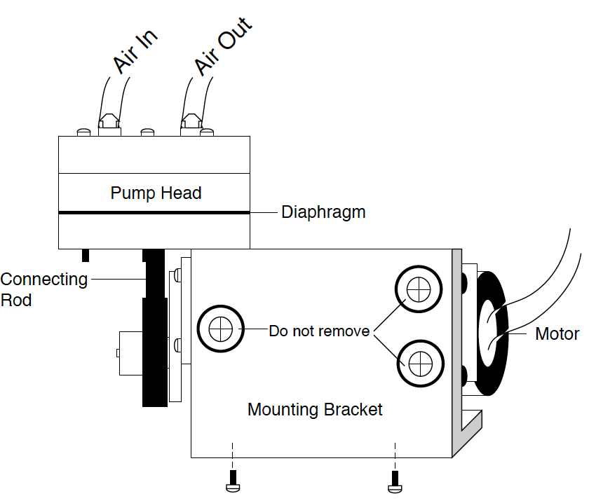
- Disconnect the inlet and outlet hoses at the quick-connect fittings; it is generally not necessary to remove the air hoses from the inlet and outlet barbs on the pump head. Disconnect the electrical harness and remove the pump.
- Remove the 4 screws on the pump head to access the diaphragm. Do not remove the 2 screws that are painted red; these screws hold the valve head assembly together.
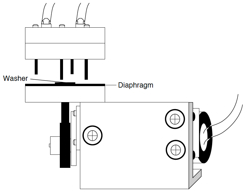
- Remove the diaphragm retaining screw and washer, and lift off the diaphragm.
- Clean the 2 surfaces of the pump head which are in contact with the diaphragm. Wash the diaphragm with warm, soapy water to remove any talc, if necessary. Apply a thin layer of the grease provided (Dow Corning 111) to the upper pump head surface.
- Reattach the new diaphragm to the connecting rod. Align the holes in the diaphragm with the holes on the bottom surface of the pump head, and hold in place while tightening the retaining screw. Make sure that the screw is flush with the surface of the washer. Tighten until the screw is snug (30 ounce-inches). The diaphragm will be curled slightly. Do not overtighten, as the diaphragm could be damaged.
- Mount the pump head and valve assembly over the diaphragm and replace the 4 screws. Tighten evenly, until the diaphragm begins to bulge slightly around the edge of the pump head assembly (36 ounce inches). Over-tightening may damage the diaphragm; under-tightening may result in leaks, or loosening of the retaining screws due to vibration.
- Install the pump on the base plate of the instrument, and tighten the screws firmly.
- Connect the electrical harness and the inlet and outlet hoses, and reassemble the base plate and LI-610 case.