
Installing the Whole Plant Arabidopsis Chamber
Printable PDF: 6400-17 Whole Plant Arabidopsis Chamber installation and operational instructions
Instructions for installing the 6400-17 Whole Plant Arabidopsis Chamber onto the LI-6400/XT Portable Photosynthesis System.
The assembly requires a Phillips head screwdriver and the included 3/32” hex key, and takes about 15 minutes to complete.
Follow these steps to install the 6400-17:
Remove the Standard Chamber
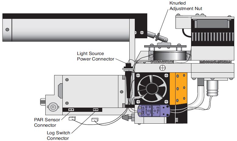
- The 6400-17 replaces the lower half of the standard leaf chamber. Remove the tripod mounting plate, if necessary, and disconnect the internal PAR sensor connector on the side of the sensor head by gently pulling straight out (Figure 1‑1).
- Use the 3/32” hex key to loosen the two long screws, and remove the top half of the standard leaf chamber (Figure 1‑2). Disconnect the purple leaf temperature thermocouple by pulling straight out (Figure 1‑1). Loosen the two screws on the lower half of the standard leaf chamber, and disconnect the lower chamber exhaust tube.
Install the 6400-17 Chamber
- Cut a piece of Propafilm from the supplied roll about 3 cm x 8 cm. With the sensor head open, position the Propafilm over the black spacer on the lower leaf chamber manifold (Figure 1‑3). Close the sensor head to secure the Propafilm. This will divert air flow away from the unused top half of the leaf chamber. Pull lightly on the Propafilm; if it moves, open the sensor head, tighten the knurled nut on the chamber tension adjustment assembly (Figure 1‑1), and repeat.
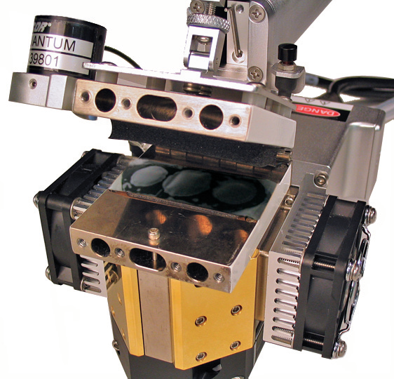
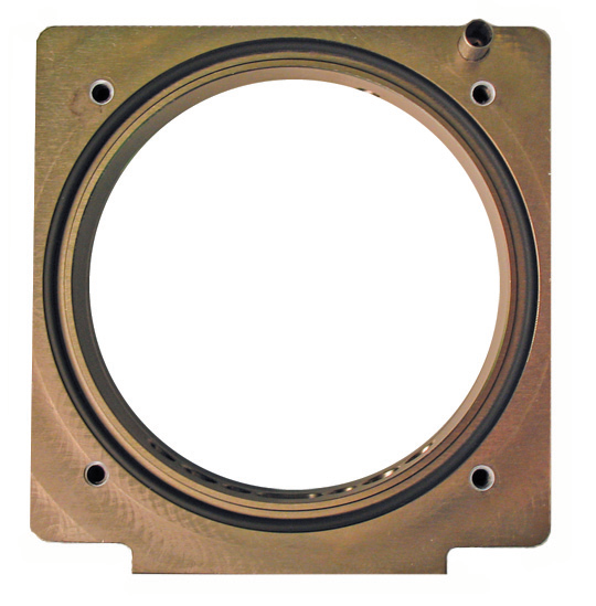
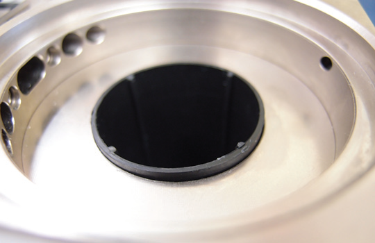
- The 6400-17 uses interchangeable bottom plates with different size apertures that accommodate either a 4 cm Cone-tainer™, or a 6.5 cm pot (Figure 1‑4). There are 4 Phillips head screws that attach the bottom plate(s) to the 6400-17. Make sure that the large o-ring on the underside of the chamber is in place before installing the bottom plate.
...and then close the sensor head tightly to hold the Propafilm in place.

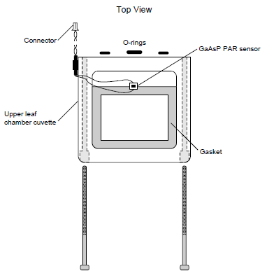
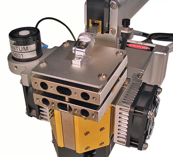
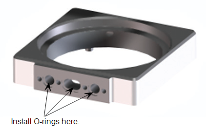
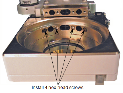
- Install two small and one large o-rings on the air passage holes on the back edge of the 6400-17 (Figure 1‑5). Use the 3/32” hex key and four 1/2” hex head screws to install the chamber to the lower leaf chamber manifold (Figure 1‑6).
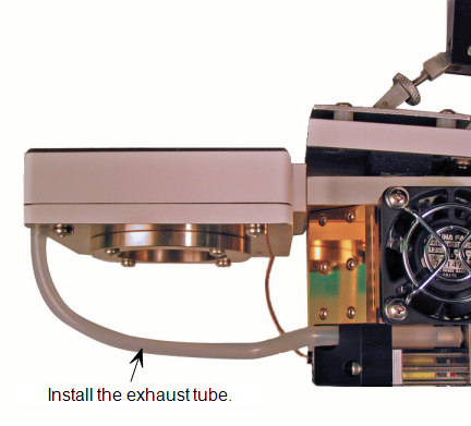
- Connect the chamber air temperature thermocouple by pushing the purple connector into the connector on the sensor head. Install either the standard exhaust tube, or the adjustable exhaust tube assembly onto the metal tube on the underside of the sensor head, and then onto the metal tube on the bottom of the 6400-17 (Figure 1‑7).
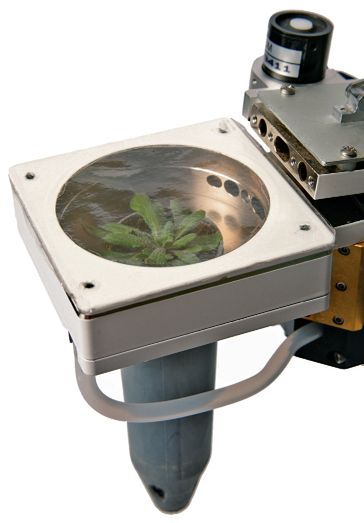
- The completed installation will appear as in Figure 8. Plant containers are inserted from the top of the chamber, and then the chamber top (with Propafilm covering) is pressed into the main body of the chamber. IMPORTANT NOTE: Insert the Cone-tainers so that only 0.5 - 2 mm of the Cone-tainer top is exposed in the chamber (Figure 1‑8). Failure to do so can result in leaks, and can obstruct air flow from the air passage holes.
Configure the Software
- The 6400-17 requires OPEN version 6.1 or above. OPEN 6.1 can be installed on 200 MHz (previous version OPEN 5.x) or 400 MHz (previous version OPEN 6.x) digital boards. Older boards require a digital board upgrade. Contact LI-COR for more details.
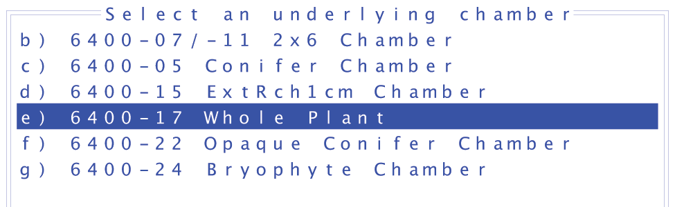
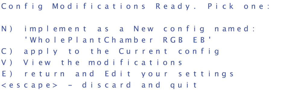
- To complete the installation, choose the Config Menu (f2) from OPEN’s main screen. Highlight New and press Enter. Scroll down to Larger Chambers, and expand the list, if necessary. Choose the 6400-17 Whole Plant. When prompted, select the desired light source, adjust the settings as desired, and then choose New (N) to save the configuration with a new name. See the LI-6400/LI-6400XT Instruction Manual, Section 8, Light Sources and Sensors, for more information.
- Choose New from the Config Menu...

- Scroll down to Larger Chambers...

- Choose 6400-17 Whole Plant...
- Adjust settings as needed...

- and press N to save as a new configuration.
Additional Information - List of Suppliers
Kord 2.5” (6.5 cm) pots and Cone-tainer™ trays can be obtained from Hummert International (Earth City, MO), as well as other on-line sources. Trays and pots from Hummert (www.hummert.com) can be found under the following catalog numbers:
RL 98 Tray (cat. #14-3480-1)
Kord 2.5” (6.5 cm) Pots (cat. #12-2250-2)
Cone-tainers can be obtained from LI-COR under part number 610-09645.