GaAsP Light Sensors
Gallium Arsenide Phosphide light sensors are used in the standard 2x3 LI-6400 chamber top, as well as many of the optional chamber tops. Standard chambers have serial numbers GA-nnn, while accessory chambers with GaAsP sensors have GB-nnn serial numbers.
Factory Calibration
The factory calibration of a GaAsP sensor is done by placing the sensor a known distance from a standard lamp, and measuring the sensor’s output. The calibration is dependent upon the spectral properties of the source (see Figure 8-23 on page 8-24 in the instruction manual). The calibration value that we provide is adjusted for a typical sun+sky spectrum, even though it is generated with a tungsten lamp.
The calibration is reported on the calibration sheet, and stored in the instrument, as the object of the CalParGaAs= configuration command. This value is used for the term ag in Equation (14-18) on page 14-10 in the instruction manual.
Generating a Calibration Correction
A calibration correction factor (fa in Equation (14-18) on page 14-10 in the instruction manual) of the GaAsP sensor in the leaf chamber can be performed for light sources not included in the Light Source menu in the Configuration list. Be warned, however, that the results are extremely sensitive to view factors and incident radiation geometry. For best results, do this procedure with incident radiation that is as perpendicular to the leaf plane as possible, and keep the radiation geometry fixed. This method does not work well with strictly diffuse light sources because of view factor differences between the center of the leaf plane, leaf edges, and the GaAsP sensor.
With due care, proceed as follows:
- Install the quantum sensor mounting bracket
- Replace the lower portion of the leaf chamber with the 9864-111 Quantum Sensor Chamber Mount (in the spares kit) using the chamber mounting screws to attach the quantum sensor mount.
- Install the external quantum sensor
- With the quantum sensor mount in place and the chamber closed, insert a quantum sensor into the mount until it contacts the leaf chamber gaskets, and secure it with the set screw.
- Orient the leaf chamber
- Orient it so that the incoming radiation is perpendicular to the leaf plane. The distance from the leaf chamber to the light source should not be changed between light sensor calibration and photosynthesis measurements. This will minimize errors due to radiation geometry and view factors.
- Set the Light Source to Sun + Sky
- This will apply no correction factor for your calibration readings.
- Record the readings
- Note the PAR values Qc (ParIn_μm ) and Qx (ParOutμm )
- Compute the correction factor
- The correction factor fa is
-
18‑2

- Enter the new value
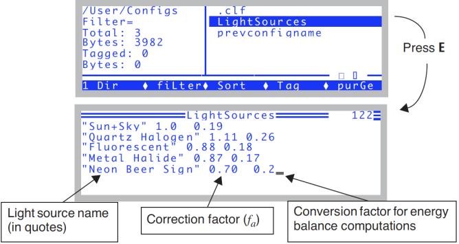
- Go to the Filer, pick the "/User/Configs" directory, highlight the file "Light Source Control" (Figure 18‑31 top). Add your new correction factor to the list, as shown in the bottom part of that figure. You’ll need a source name in quotes, followed by the fa value, followed by a guess at the absorbed energy factor (αk in Eqn (17-3) on page 17-2 in the instruction manual). Use 0.2 unless you have measured it. Press escape then U then Q when you are done.