
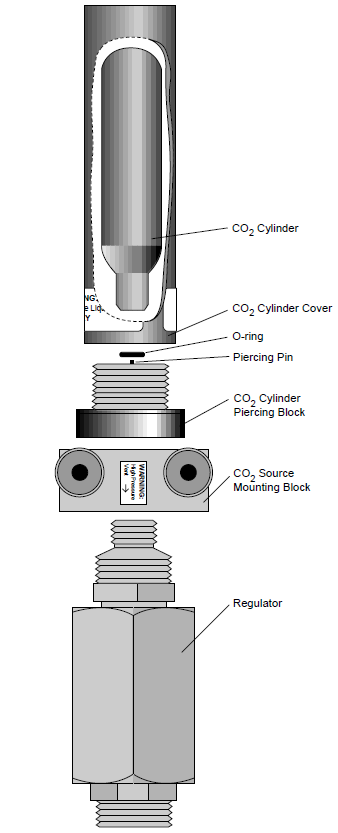
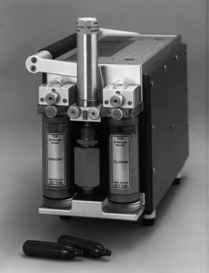
CO2 Source Assembly
CO2 Source Assembly Replacement
Instructions for installing the CO2 source assembly.
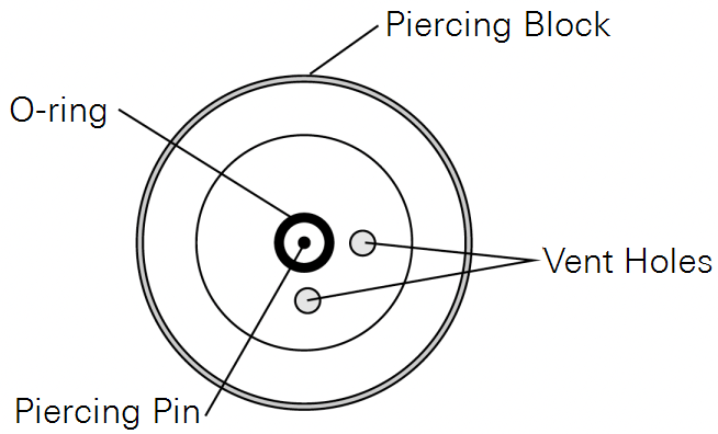
Important Note: Although the O-ring may perform properly for several cylinders, we recommend that it be replaced with each new cylinder. After being subjected to several high pressure cycles the O-ring will weaken and become perforated, and will more easily tear or split. If the O-ring is slightly torn or perforated the gas will slowly leak through the vent hole and shorten the life of the cylinder. If the O-ring is split, the gas will rapidly vent until empty.
- Place a new CO2 cylinder into the cylinder cover, large end first.
- Screw the cylinder cover into the piercing block. You may feel some resistance as the piercing pin makes contact with the cylinder. A short burst of venting CO2 may occur as the cylinder is pierced; the leak will be minimal if you continue to quickly tighten the cylinder cover.
Oil Filter Replacement
Inside the CO2 cylinders, there is a small amount of residual oil from the manufacturing process. When the CO2 cylinder is pierced, some of this oil is released along with the CO2. There is a filter attached to the regulator to prevent oil from clogging the flow restrictor. After using 25 CO2 cylinders, the oil filter should be replaced. Instructions are given below. If the filter is not replaced, the flow restrictor may become clogged, severely restricting flow.
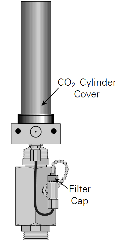
Warning: Before replacing the filter, the CO2 cylinder cover must be removed in order to depressurize the 6400-01 CO2 Injector. If you attempt to remove the filter cap before the cylinder is exhausted, high pressure CO2 will blow the filter out of its holder.
Filter Installation
- Remove the CO2 cylinder cover.
- After depressurizing the CO2 cylinder, remove the filter cap to reveal the filter.
- Use the filter hook included to carefully pluck out the old filter, trying not to scratch the O- ring seat.
- Remove the paper from around the new filter.
- Roll the filter between your thumb and index finger to smooth and compress it to a diameter that just fits into the body of the “T” fitting on the regulator.
- Insert the filter and push it into the body. Do not use the filter cap to push the filter into the body because some of the filter fibers can become tangled in the O-ring seal and cause leaks.
- Reconnect the filter cap.
Making Your Own Filters
The oil filters are simply cigarette filters that can be cut from any unused filtered cigarette. When cutting the filter, use a razor blade to cut a 2 cm (3/4 inch) piece of the filter. Slit and remove the paper, and insert the filter as described above.