Remote Control
- Terminal Software (complete control)
- The computer acts like a terminal to the LI-6400, providing all of the normal front-panel capability locally or even over the internet. The connection can be via Ethernet or RS-232. The instrument can continue to be used from the front panel, as well as from the computer. This is described in Using LI6400XTerm and Using LI6400Group.
- Send LPL Commands (very limited control)
- The LI-6400 can be made to compile and execute incoming LPL commands via RS-232 while OPEN is running. This provides a method for an external device to have as much or as little control as is desired. For example, a computer controlled imaging system could provide the LI-6400 with leaf areas, and trigger logging events. This method is described in Control via LPL Commands.
Using LI6400XTerm
The program LI6400XTerm allows you to connect to any LI-6400XT on your local area network (Ethernet) to passively monitor and/or actively control. Further, a single LI-6400XT can support any number of such connections simultaneously. The LI-6400XT does not need to be in any special mode of operation - you can connect or disconnect at will.
The program can also connect with RS-232, and this allows it to connect to any LI-6400 that has version 5.3 software or above. The RS-232 connection requires that the LI-6400 have LTerm active (press L from OPEN’s main screen).
- Launch the program
- (Windows) Double click the shortcut icon on the desktop, or find the program under Start menu | All Programs | LI-6400_Apps.
- (Mac OS X) The program will be in the
/Applications/LI-6400Apps/folder. - (Linux) The program is in the Applications | Education menu.
- Connect to an LI-6400
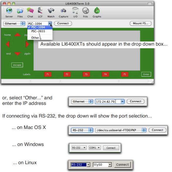
- Pick the host name, and click the Connect button.
- The display is duplicated on your PC
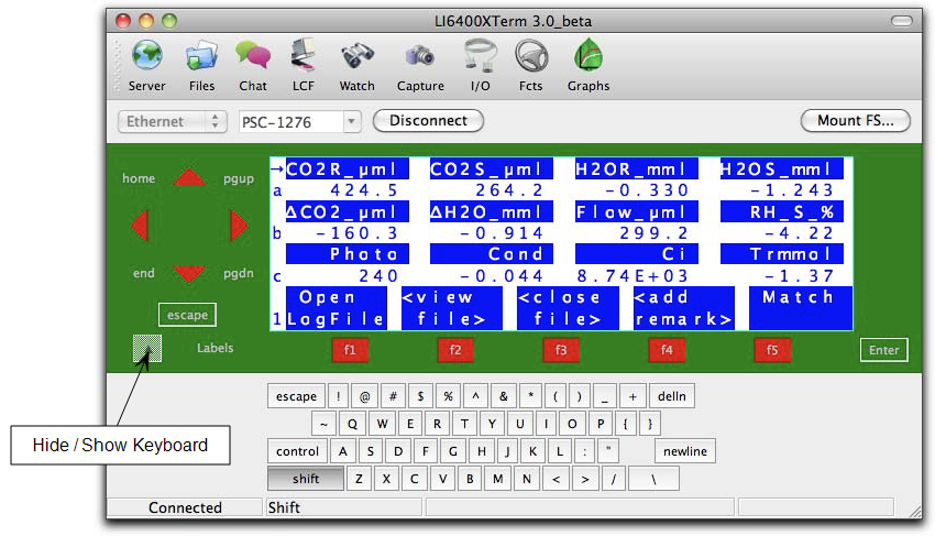
- Once connected, the display will show exactly what is on the instrument’s display. The buttons around the simulated display will behave just like on the instrument (Figure 11‑30).
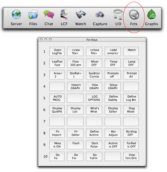
- Function Keys
- LI6400XTerm can display all available function keys as active buttons.
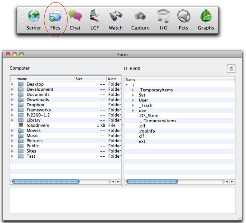
- File Transfers
- Use drag and drop to move files between the computer and the LI-6400 (Figure 11‑32).
Using LI6400Group
LI6400Group is similar to LI6400XTerm, except it allows you to monitor/control multiple LI-6400s. A user guide is available under Help in the menu bar.
- Launch the program
- (Windows) Double click the shortcut icon on the desktop, or find the program under Start menu | All Programs | LI-6400_Apps.
- (Mac OS X) The program will be in the /Applications/LI-6400Apps/ folder.
- (Linux) The program is in the Applications | Education menu
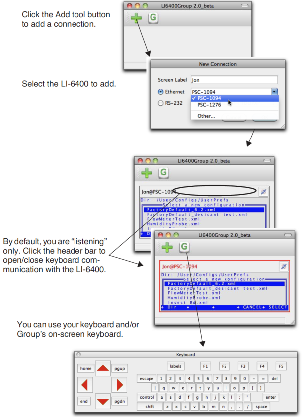
- Add a connection
- Click the add connections button to add as many LI-6400 connections (Ethernet or RS-232) as you wish.
- At this point, it is just like the LI6400XTerm program. If you type with the main window active, those keystrokes will be sent to the instrument if the control connection is enabled (red box around display). The difference is you can add more connections.
- Add another connection
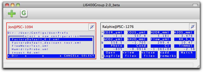
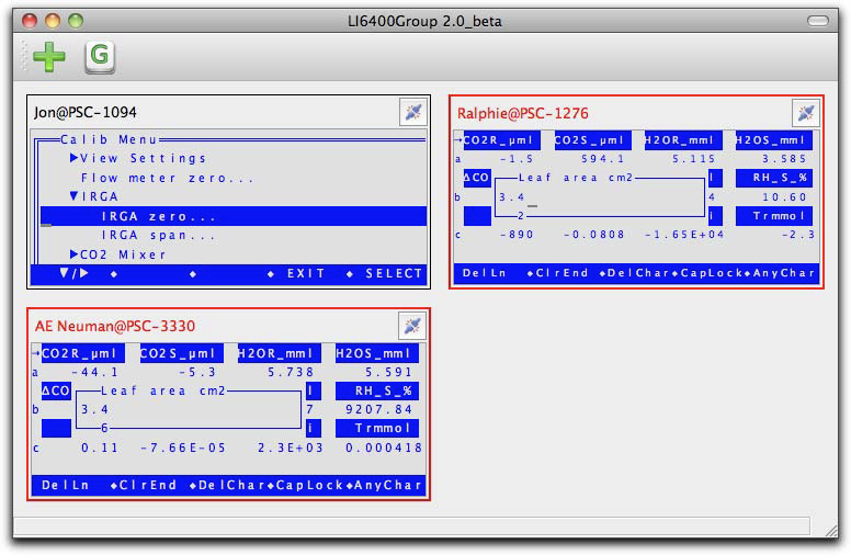
- Click the add button and add another connection. The window will resize to accommodate it. (In the preferences dialog, you can select the number of columns to allow.)
- Simultaneous control
- Click on a display header bar to enable/disable it accepting key strokes (when enabled, the entire display will be bordered in red).
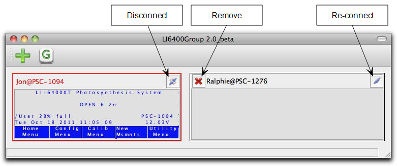
- Disconnecting
- Click a display’s disconnect button to stop communications. You can click again to re-establish (with the same or another instrument). An inactive display can be removed by clicking the remove button.
Control via LPL Commands
Suppose you have a data logger, or a data logging computer, that you want to coordinate somehow with the LI-6400. For example, you may want to get an occasional value of CO2 or photosynthesis, or have the computer tell the instrument to start or stop an AutoProgram.
One of the fields in the Comm Port configuration lets you enable a mode whereby you can send and receive data while the LI-6400 is otherwise going about its business (Figure 11‑37).
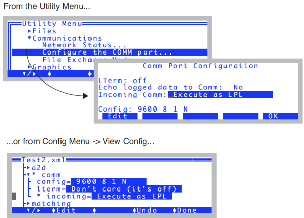
Note: Changes to “Incoming Comm” mode do not take effect until you return to OPEN’s Main Screen.
The incoming data should consist of LPL commands. LPL is the language that all of the OPEN programming is written in (refer to Part VI, Programming), so this option provides great flexibility. While “Execute as LPL” is enabled, every time the LI-6400 receives a newline character (decimal 10), it attempts to compile and execute the data that has been received since the last newline. Thus, if you sent the following line
"Hello from the LI-6400\n" comm print
followed by a newline, the string
Hello from the LI-6400
would be sent out the LI-6400’s Comm port, followed by a newline character. Notice, we embedded a newline character into the output string by slash-n (\n).
Getting The Values of Variables
Many of the variables of interest in OPEN have ID numbers associated with them. (See Chapters 14 and 15 for a discussion of system and user defined variables.) A very useful way of getting any of these variables sent out the Comm port in a nicely formatted fashion is to use the function idout, which expects a destination and an ID number on the stack. For example,
30 comm idout
will get the following in return:
Photo= 12.34
The function idout prints the log format label for that value, followed by a ’=’, followed by the present value of the variable, formatted just as for a log file, followed by a newline character. You can get multiple values by putting an array of id numbers on the stack:
:INT { 30 -1 -2 -4 -5} comm idout
will result in
Photo= 12.34
CO2R= 378.1
CO2S= 372.3
H2OR= 12.34
H2OS= 20.45
If you know the variable name of something (see Table 14-10 on page 14-23 in the instruction manual lists system variable names and ID numbers, but this applies to any public variable in OPEN), you can create an output line formatted however you choose. For example, the variable name that holds leaf area is area_cm2. Thus, if you want the value to be digits with no other label, you can send area_cm2 "%1.5f\n" comm print to receive
1.23456
The variable name for user defined items is usually unnn, where nnn is the ID number. Thus, photosynthesis is u30, and transpiration is u20.
Setting the Values of Variables
You have to be a little careful here, since many of the user defined variables are recomputed once or twice a second, so setting a value won’t accomplish very much. For example, you could tell the LI-6400 to make the value of photosynthesis 20.00, but it would only stay that way a fraction of a second until it was computed again. User defined constants and remarks are a different matter, since they are strictly determined by outside influences - i.e., a user typing on the keyboard. Control set points are also a different matter, since many of them have functions for getting and setting, as we’ll see in Control Set Point Variables.
In general, variables are set in LPL by the following statement:
<value> &<variable name> =
The first item pushed onto the stack is the desired value. Next comes the address of the variable to be set, then finally an ’=’ sign. For example
2.34 &area_cm2 =
will set the area to 2.34. The & before area_cm2 is important. That tells the compiler to put the address of that value on the stack, rather than the value of the variable. (Note: setting area in this way will not by itself change the f1 level 3 function key label, but it does change the area.)
There is a handy function for converting variable ID numbers to addresses: FmtGetVarAddr. Thus, you can set any system or user variable using only the ID number. For example, leaf area (area_cm2) is -33, so
2.34 -33 FmtGetVarAddr =
would accomplish the same thing as
2.34 &area_cm2 =
and
2.34 30 FmtGetVarAddr =
is the same as
2.34 &u30 =
which (pointlessly) sets the photosynthetic rate.
Control Set Point Variables
Information about LED Source control, flow control, temperature control, and humidity control can be obtained and changed remotely. See LED Source Control on page 25-22 in the instruction manual and subsequent sections for a number of useful functions, designed for use with AutoPrograms, but serve nicely for remote control as well. For example, you can use LampGetTarget in the sequence
LampGetTarget "Type=%d, Val=%f\n" comm PRINT
to learn
Type=2, Val=2000
which means the lamp is in constant PAR control (Type=2) with a set point (Val=) of 2000 μmol m-2 s-1.
To set a control and setpoint for the lamp, you can use LampSetTarget or LampSetNewTarget. The former just changes the target, and the latter changes both the control type and the target. For example,
1500 3 LampsetNewTarget
changes an LED light source to constant control signal (3) mode, with a target of 1500 mV. If the device is an LCF, it sets it to fixed blue mode, with a target (red + blue) of 1500. This function does not output anything, but if you want some sort of verification sent out the comm port, you could add it yourself:
1500 3 LampsetNewTarget "Set Lamp!\n" comm PRINT
or
1500 3 LampsetNewTarget LampGetTarget "Type=%d,Val=%f\n" comm PRINT
The command lines can be as long as you like, as long as no newline characters are present until the end.
LCF Control
Refer to Programming Commands on page 27-86 in the instruction manual, which describes commands such as
DoFsFmp
which will trigger the measurement of Fs and Fm'.
Variables and Commands for Logging
Any of the LP_ commands (Chapter 25 in the instruction manual), such as LPLog, can be used with the “Execute as LPL” option. Thus, if a log file is open, an external device can force a data record to be logged by sending
LPLog
If you want to send a string to be added to a log file as a remark, do this:
"The sky is falling!" LogTSRemark
Testing Commands
It is wise to test the commands you will be using, before you commit them to code in your data logger or computer program. A convenient way to do this testing is with LI6400XTerm or LI6400Sim (below) or Telnet (next section).
- Use LI6400XTerm and an LI-6400
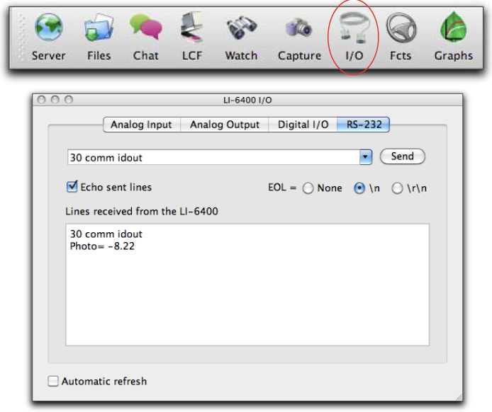
- Establish the connection (Using LI6400XTerm). Then, enable the incoming LPL option (Figure 11‑37) and return to OPEN’s main screen. Finally, open the Comm Monitor window. Enter commands in the upper window, see results in the lower (Figure 11‑38).
- Use LI6400Sim by itself
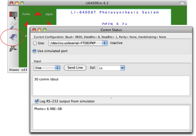
- Using the Windows simulator, enable the incoming LPL option (shown in Figure 11‑37) and return to the OPEN’s main screen. Then, open the Control window, then click on the Comm tab. Type in the upper window, see results in the lower (Figure 11‑39).
- Use Telnet
- With your PC and the LI-6400XT on the same LAN, determine the IP address of the LI-6400XT, and launch Telnet from a command line prompt on your PC. Be sure to specify port 6409.
-
$ telnet 172.24.81.168 6409
- A successful connection results in a message like
-
Trying 172.24.81.168...
Connected to 172.24.81.168.
Escape character is '^]'.
- To send a command, simply type it on the PC, followed by return. In this mode (Telnet using port 6409), RS-232 output form the LI-6400XT is sent to your PC, and anything you type on the PC is sent to the XT.
- To exit Telnet, type ctrl + ], then q.