Chemical Tubes
The chemical tubes can be left in place on the console until it is time to replace the chemicals, or to service a tube’s flow control assembly.
Removing
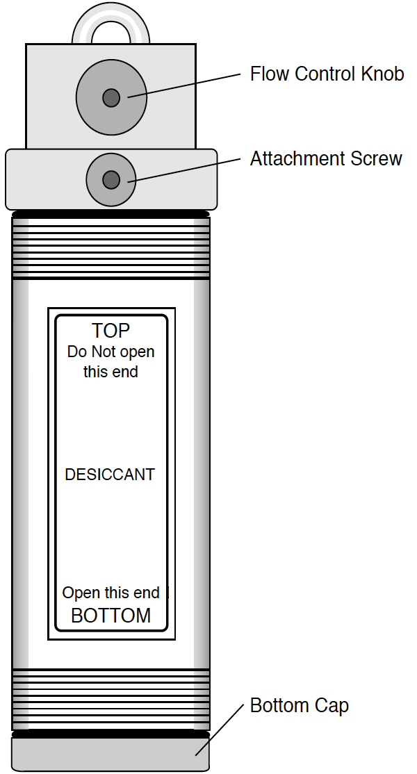
The tubes are removed from the console by loosening the attachment screw (Figure 19‑1). If the screw is too tight to turn (and you should be turning it counterclockwise, as viewed in Figure 19‑1), then before you resort to pliers, try wiggling the bottom of the tube left and right (orientation as shown in Figure 19‑1) as you attempt to loosen the screw.
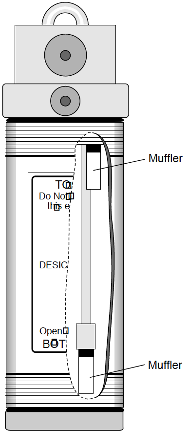
Important: To open a tube to replace its chemicals, turn the tube upside down and unscrew the bottom cap. Damage to the mufflers (Figure 2) will result if you unscrew the top cap with chemicals in the tube. Fill to within 1 cm of the end of the tube with Drierite (desiccant tube) or soda lime (soda lime tube). Both chemicals are in the spares kit.
Cleaning The End Cap Threads
It is important that the threads be kept very clean. If dust or other debris accumulates on them, you will have a difficult time putting the end cap on far enough to compress the O-ring, and the tube will leak. This is most often a problem with the desiccant tube, and can show up as instability in the CO2 concentration in both reference and sample cells.
After you dump out the old chemicals from a tube, use a stiff brush to clean the threads of both the end cap and the tube barrel. For especially dirty threads, soak them in water briefly, then wipe them clean and dry.
Do not lubricate the threads. Lubricant will accumulate dust, and aggravate the problem. When you reassemble the tube, make sure the threads are clean and dry. No grease, please.
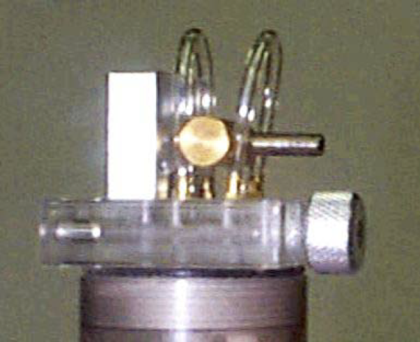
Replacing the Air Mufflers
There are two air mufflers attached to the air hoses inside the chemical tubes (Figure 19‑2). These mufflers may become clogged, restricting air flow through the tubes and thus reducing the maximum flow rates. (This is one of several things that can reduce flow rates. See Can’t Achieve High Flow Rates.)
To replace the mufflers, remove the bottom cap, empty the chemicals and then remove the top cap. The old mufflers can then be unscrewed and replaced with new ones. The white part is glued to the black part and will break loose, if you try to screw or pull it out while holding the white part. Use a 1/4” wrench and touch only the black threaded end. Do not overtighten the mufflers, as they can break at the threads very easily. There are air mufflers in the spare parts kit.
The Desiccant Tube: Use Drierite
To regenerate Drierite
LI-COR recommends indicating Drierite (W.A. Hammond Drierite Company, P.O. Box 460, Xenia, OH 45385) for use with the LI-6400. Drierite is anhydrous 97% calcium sulfate (CaSO4) and 3% cobalt chloride. Calcium sulfate is safe, chemically inert except toward water, economical, and can be regenerated. Drierite absorbs approximately 6.6% its weight in water. Indicating Drierite is blue when dry, and changes to pink upon absorption of water to signal when it should be replaced.
- 90 minutes at 230 °C or 450 °F
- Preheat the oven and a shallow pan. Spread the granules in a single layer one granule deep and heat for the above time period. (Note: less heat for a longer time will not work.)
- Seal in a glass container while still hot
- After 90 minutes, place the hot, regenerated material back in its glass container and close the lid.
- Note that the color of the indicating Drierite may become less distinct after successive regenerations. If it turns black, you’ve overheated it.
The CO2 Scrub Tube: Use Soda Lime
Soda lime (calcium oxide and sodium hydroxide) removes CO2 from the air stream, and adds a bit of water. Some brands add more water than others. When soda lime becomes very dry, it loses efficacy. This is not typically a problem for the LI-6400, since incoming air, which generally has some moisture in it, goes through the soda lime first.
Wet soda lime is available in the spares kit. The part number is 9964-090.
How often the soda lime needs to be replaced depends upon how much CO2 it has been forced to remove. Loss of capacity to scrub CO2 can be recognized by an inability to reduce the CO2 mole fraction to zero and hold it there.
A Quick Soda Lime Test
Turn the soda lime tube on full scrub, and wait for the reference CO2 to get as low as it will go. Then blow a puff of air at the inlet tube on the right side of the console, and watch the reference CO2 reading. A positive spike of more than 2 ppm would indicate that the soda lime should be changed.
Reattaching
Here’s a quick checklist for reattaching the tubes:
- Chemicals to 1 cm of the top.
- Leave a little room for them to move when shaken. Then you can easily break up channeling, which is the tendency for air to find a dominant passage through the chemicals, thereby saturating the chemicals unevenly in the tube.
- Threads clean and dry
- Discussed in Cleaning The End Cap Threads.
- Are the end cap O-rings slightly compressed?
- Not too tight, but no gaps allowed.
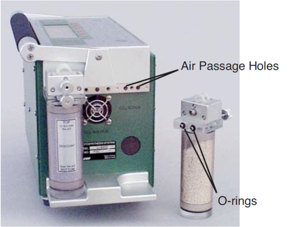
- Make sure the air passage tubes have O-rings
- See Figure 19‑3. Also, make sure that the mounting surface on the console is clean.
- Not too tight
- The attachment knob should be just slightly snug, to squeeze the air passage O-rings a bit. Finger tight is fine, and never use pliers. Don’t be concerned if the tube is not rigidly held against the console. A bit of wobble is normal.
Chemical Tube Flow Control
The usual reason to take apart the flow control assemblies on the soda lime or desiccant tube is that one of the small flow tubes becomes pinched, or some debris clogs up the tubing, or gets in the small air passage ways.
To disassemble and service a flow adjustment assembly
- Set the flow adjust knob
- Put it midway between SCRUB and BYPASS.
- Remove the knob
- Use a 5/32 hex key to hold the flow adjust bolt, and loosen the flow adjust knob with channel lock pliers. (Turn the nut toward SCRUB to loosen.) Remove the nut and white washer that is beneath it.
- The flow adjust knob has to go back on oriented the same way, so you should mark which face is out when it is attached. (The knob has a set screw (142-00109) inserted from the outside that sets the proper depth of the flow adjust bolt. Don’t adjust the set screw.)
-
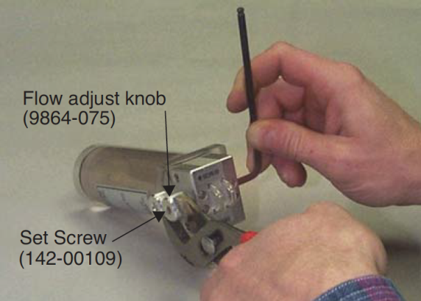
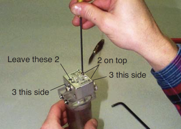
Figure 19‑4. Removing the flow adjust knob. - Remove eight screws
- Using a 3/32 hex key, remove the three screws on each side of the assembly, and two of the four screws from the top. Leave the two top screws that are closest to the flow adjust bolt side (opposite the side where the nut was) of the assembly.
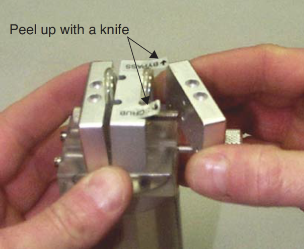
- Remove the outer and center pieces.
- You’ll have to peel the ends of the SCRUB and BYPASS stickers up with a knife, then the two loose pieces of the assembly can be removed.
- Service as needed
- If the small tubing remains compressed long enough (especially in hot weather), they can seal closed. If that is the case, replace them. Also, check carefully in the hose barbs and air passages in the clear plastic base of the assembly for any debris that might be lodged there, blocking the flow.
- The small tubing is polyurethane, 1/16" inside diameter, and 1/8" outside diameter.
- Reassemble
- Reverse the procedure. When it is time to reattach the flow adjust knob, remember to put the white washer on first, and be sure the knob is oriented correctly. How do you tell? There is a set screw threaded into the knob; the back of the set screw accepts a 3/32 hex key (don’t turn it!), and this is the side that should face away from the flow control assembly.