Servicing the External CO2 Source Assembly
Oil Filter Replacement
Inside of every CO2 cartridge is a residue of oil. When the CO2 cylinder is pierced, some of this oil is released along with the CO2. There is a filter attached to the regulator to prevent oil from clogging the flow restrictor. After using 25 CO2 cylinders, the oil filter should be replaced. Instructions are given below. Note: Some brands of cylinders (notably CopperHead™ and Curtis™) contain considerable oil, requiring a filter change every cartridge. It is therefore good policy to check the filter (remove cap and look for discoloration on the filter end) every time you replace a cylinder when using non-LI-COR cylinders.
To install the filter:
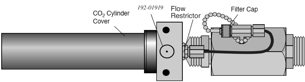
- Remove the CO2 cylinder cover.
- Warning: Before replacing the filter, the CO2 cylinder cover must be removed in order to depressurize the 6400-01 CO2 Injector. If you attempt to remove the filter cap before the cylinder is exhausted, high pressure CO2 will blow the filter out of its holder.
- Remove the filter cap
- After depressurizing the CO2 cylinder, remove the filter cap to reveal the filter (Figure 19‑34).
- Remove the old filter
- Use the filter hook included to remove the old filter, being careful not to scratch the O-ring seat. (Hint: pointed tweezers work better.)
- Prepare the new filter
- Remove the paper from around the new filter. Roll the filter between your thumb and index finger to smooth and compress it to a diameter that just fits into the body of the “T” fitting on the regulator.
- Install the new filter
- Insert the filter and push it into the body. Do not use the filter cap to push the filter into the body because some of the filter fibers can become tangled in the O-ring seal and cause leaks.
- Reconnect the cap
Rolling Your Own…
The oil filters are simply cigarette filters that can be cut from any unused filtered cigarette. When cutting the filter, use a razor blade to cut it 2 cm (0.75 inch) long. Then slit and remove the paper, and insert the filter as described above.
Getting To Know Your Mixer
It is a good idea to keep a record of the dynamic response of your mixer. Specifically, you should monitor how long it takes to go from 100 to 2000 μmol mol-1. With use, oil may get past the filter and begin to clog the flow restrictor in the source. If this happens, the time it takes to make this 100 to 2000 μmol mol-1 transition will increase (Eventually, you won’t even be able to get to 2000 μmol mol-1). By measuring this transit time periodically, you can get an indication of coming problems before they can actually occur, and can avoid them entirely by servicing the source as described in the next section. Example: a new source (clean restrictor) might make this 100 to 2000 transition in 2 minutes. If after a while this time degrades to 3 minutes, then replacing the flow restrictor would be in order. This is covered in the next section.
If the Flow Restrictor Becomes Clogged
If the oil filters are not replaced on a regular basis, oil from the CO2 cartridges can enter the copper supply tube and clog the flow restrictor. If you are unable to attain desired CO2 concentrations while operating the CO2 injector, and you are using a fresh CO2 cartridge and oil filter, you may have a clogged flow restrictor. If oil makes it through the flow restrictor and enters the console, it will require factory service. Therefore, it will behoove you to keep close watch on your filters, to prevent any of this from happening.
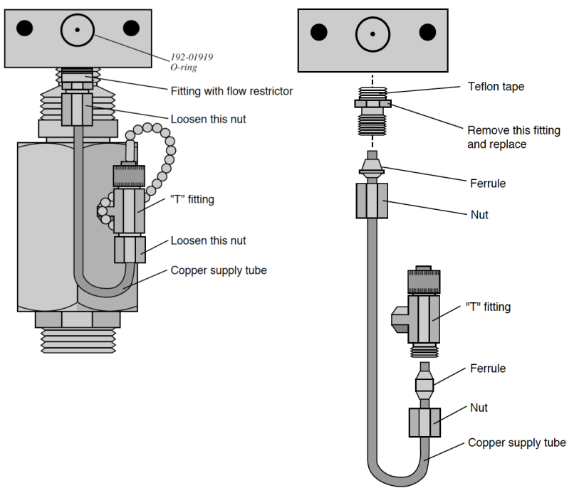
The flow restrictor must be replaced if it becomes clogged. The restrictor is pressed into the fitting connected to the top of the copper supply tube (Figure 19‑35), and cannot be removed; you must replace the entire fitting. A spare fitting with the restrictor in place (part number 9964-042) can be found in the 6400-01 spare parts kit.
To replace the flow restrictor and clean the copper supply tube:
- Loosen two nuts, remove supply tube
- One is at the base of the “T” fitting (Figure 19‑35), and the other is at the top of the copper supply tube.
- Clean the supply tube
- To remove any oil that may be present in the copper supply tube, flush thoroughly with an organic solvent (e.g. acetone) that leaves no residue. If that’s not possible, use hot, soapy water (dishwashing soap works well), and rinse thoroughly with clean water.
- Blow out the tube to ensure no droplets are left inside. If any droplets get up into the flow restrictor, it will become clogged.
- Replace the flow restrictor
- Remove and discard the fitting containing the flow restrictor. Install the new fitting/restrictor (LI-COR part #9964-042). Note that the fitting is wrapped at one end with Teflon tape (Figure 19‑35). Insert this end into the mounting block and tighten securely.
- Install the copper supply tube
- Tighten the two nuts.