The Chamber Handle
Handle Maintenance
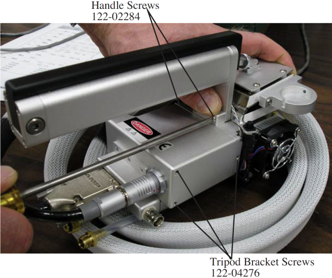
Handle maintenance is simple. The handle is held on with two screws (or three, depending upon the instrument’s vintage). If they get loose, tighten them (Figure 19‑17).
Latch Maintenance
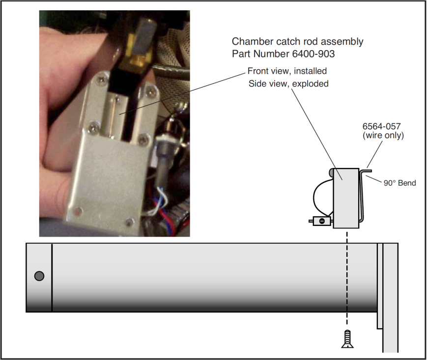
The key to the latch mechanism is the chamber catch rod, that little wire shown in Figure 19‑18. There are a couple of latching problems that this rod can cause:
- Chamber doesn’t latch reliably
- This rod must have a 90 degree bend at the top, or the chamber will not latch correctly. If it becomes straightened, reach in with a pair of needle nosed pliers and re-bend it.
- Chamber doesn’t unlatch reliably
- If the rod isn’t far enough to the left (Figure 19‑18) when the chamber is open, then you might have trouble getting it to unlatch. Hint: If you have trouble unlatching a chamber, just push the black handle piece to the left (looking down on it from the rear) as you squeeze the handle.
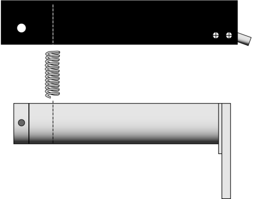
Latch Return Spring
The latch return spring is shown in Figure 19‑19. It should never need any service, and the only reason you might have to deal with it is if the spring should fall out of place when the handle is disconnected.
Handle Removal
The handle must be removed for certain service operations, and for installing certain chambers (e.g. the 6400-09 Soil Chamber and the 6400-05 Conifer Chamber).
To remove the chamber handle assembly
- Detach the chamber top from the handle
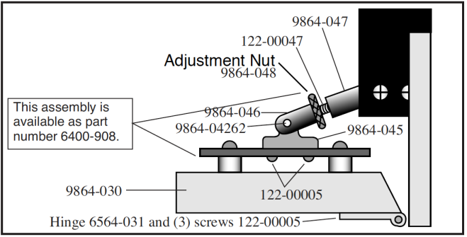
- Open the chamber, and turn the adjustment nut until it is free of the handle (Figure 19‑20).
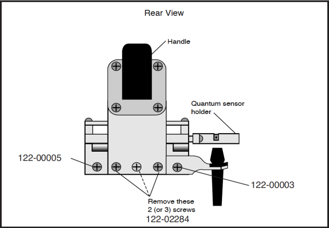
- Remove the handle screws
- The screws are located on the back side of the handle, as shown in Figure 19‑21. Use a #1 Phillips head screwdriver to remove them. Note that the middle screw (if there is one) is shorter than the other two. Allow the handle to rest at the side of the sensor head with the log button attached.