
Replacing the Mixing Fan
NOTE: A video that describes how to change the mixing fan is available at: licor.com/support/LI-6400/videos/changing-mixing-fan.html
Open the Optical Bench
You will need a set of small hex keys, a #1 phillips screwdriver, and a pair of tweezers.
- Remove the handle from the sensor head.
- Detach the chamber top from the handle.
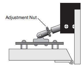
- Open the chamber, and turn the adjustment nut until it is free of the handle.
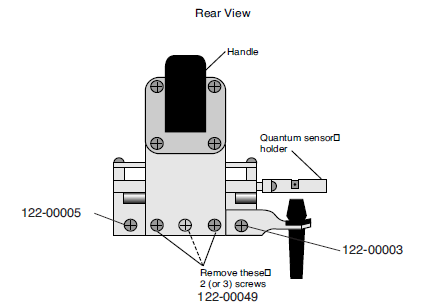
- Remove the handle screws
- The screws are located on the back side of the handle. Use a #1 Phillips head screwdriver to remove them. Note that the middle screw (if there is one) is shorter than the other two. Allow the handle to rest at the side of the sensor head with the log button attached.
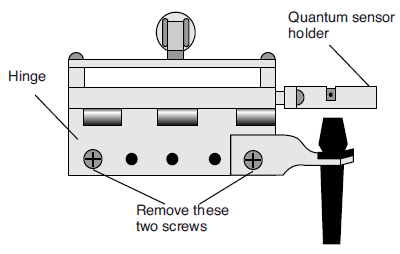
- Remove the upper half of the leaf chamber.
- Remove the two screws from the hinge on the rear of the upper half of the leaf chamber (Figure 19-31). The upper portion of the leaf chamber can now be moved aside; unhook the connector from the PAR sensor or LED Light Source, if necessary.
- Remove the optical bench cover.
- Pull off the air hose from the underside of the leaf chamber. Remove the male end of the thermocouple connector by pulling straight out.
- The next step is to turn the IRGA over and access the fan motor cover and the fan power connections.
Removing the Old Motor
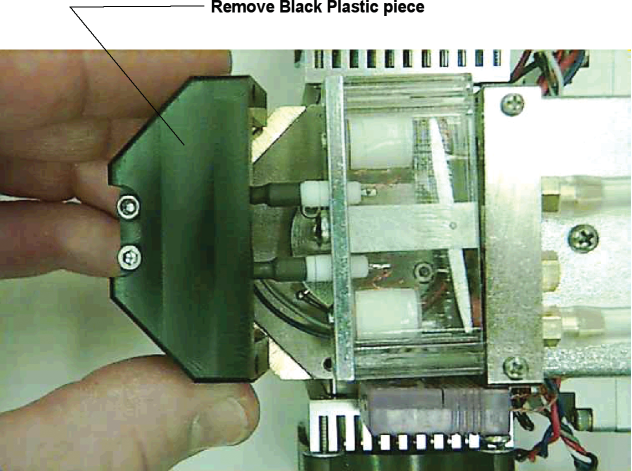
- Use a 3/32” hex key to remove the four screws that hold the black plastic housing on the bottom of the block assembly, toward the front of the IRGA.
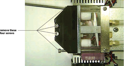
- Remove the two longer screws, and lift the black plastic housing piece off.
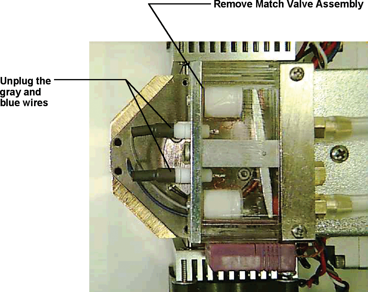
- Remove the blue and gray wires from the match valve assembly by unplugging them from the metal base plate of the match valve. Set the match valve assembly aside. Be careful NOT to remove the clear plastic cover from the assembly. Note that there is a hole in the clear plastic cover on one side. This is the side that faces the motor cover.
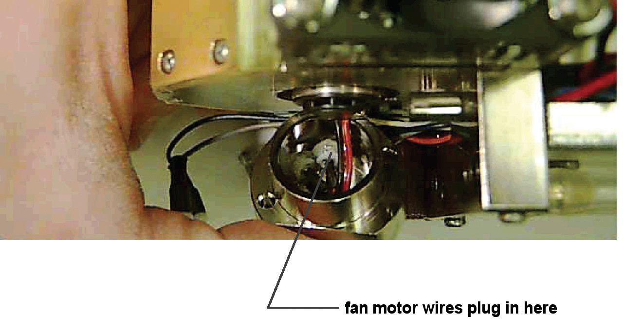
- Remove the two screws from the fan motor cover using a 5/64” hex key and lift the cover up enough to see where the motor wires plug into feed-throughs inside the cover. You will not be able to remove it completely at this point.

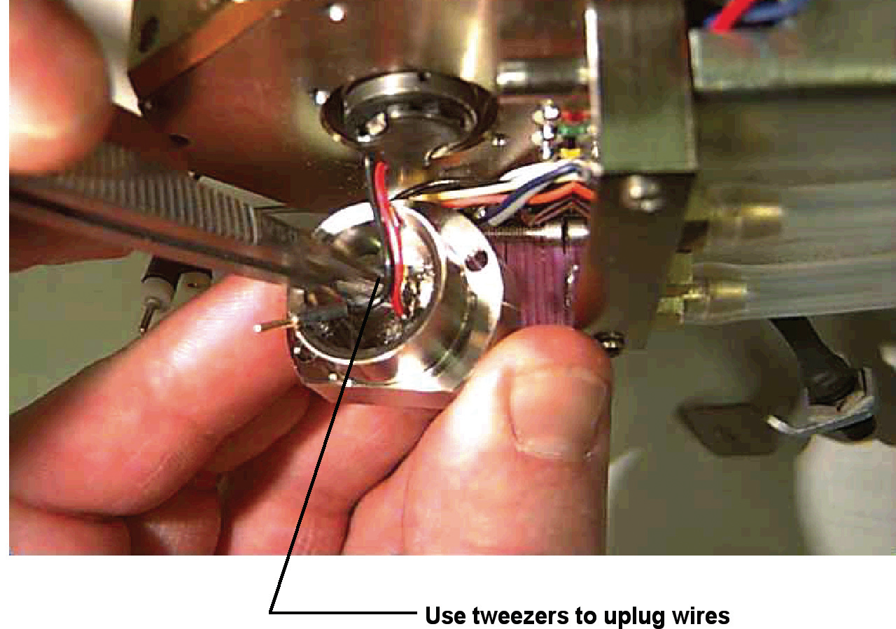
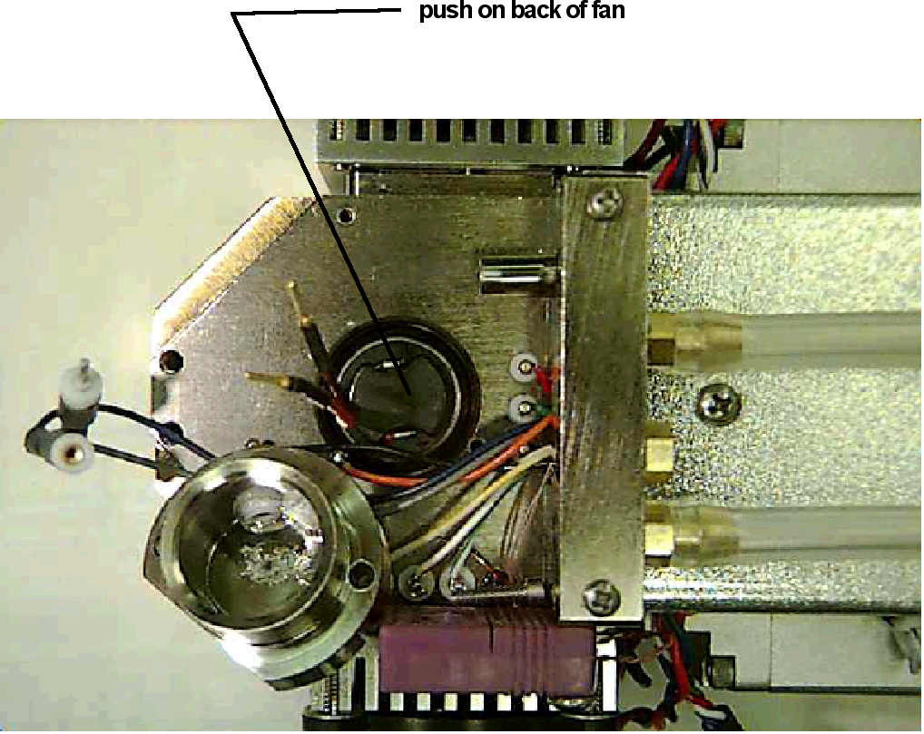
- Note the orientation of the red and black (or solid red and red with a black stripe) wires from the fan motor and unplug them with the tweezers from the inside of the motor cover. Red goes to orange and black to black (or solid red to orange and red with a black stripe to black).
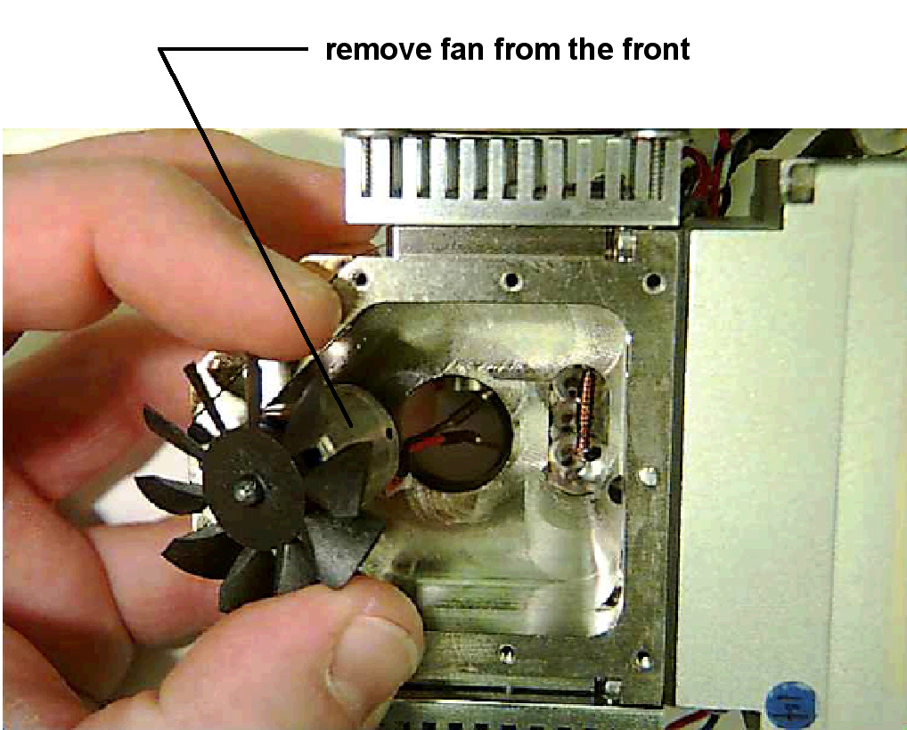
- With your finger, push on the back of the fan motor and slide it on through the hole. Note the “O” ring that holds the motor and be sure it is in place.
Installing the New Motor
Note: Before handling the fan motor assembly be aware that the motor shaft is very small diameter and very hard metal. Slight side pressure can easily break the motor shaft. Exert pressure only straight along the axis of the shaft.
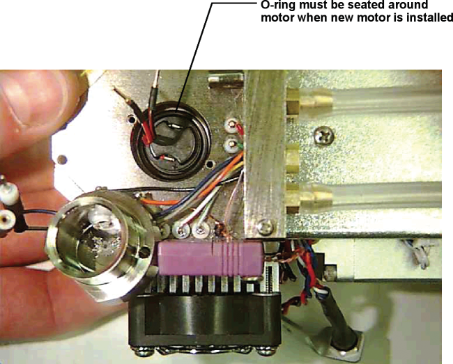
- Slide the new fan assembly in from the top and lay the O-ring around the motor, in the recessed hole.
- Plug the black and red (or black and red with a black stripe) motor power wires into the sockets on the inside of the motor cover. Red goes to orange and black-to-black (or solid red to orange and red with a black stripe to black).
- With one hand, hold the end of the motor shaft (center of fan blades) with the tip of a finger while seating the motor cover with the other hand. Use a thin object to poke the O-ring down into the bottom of the hole. Allow the motor to rotate on your fingertip, if needed, to allow the wires to “find” their most relaxed position as you seat the cover. Install the two screws to hold the cover. Be careful not to pinch any wires in the process. Turn the screws to the point where they stop, but do not tighten completely.
- Turn the entire assembly over and gently turn the fan blades with your finger. They should turn freely.
- Lay the optical bench cover on the top of the block and hold it down firmly. Reach into the center hole with a long thin object and gently turn the fan blades. It should turn freely. You want the depth of the insertion of the fan motor in the hole such that it will not rub on the bottom of the cell volume, or on the shroud piece attached to the optical bench cover. If you need to push the motor in more, be certain to only press straight in on the motor shaft.
- Install the optical bench cover. Be sure that the nylon gasket is properly aligned and install the 8 screws to attach the optical bench cover.
- Repeat the test to be sure that the fan blades turn freely using the thin object to turn them. Now turn it back over and tighten the two screws that hold the motor cover. Repeat the fan blade rotation test. If ok, reinstall the match valve assembly and plug in the blue and gray wires. Be sure that the side of the clear plastic cover of the match valve assembly with the hole faces towards the fan motor cover.
- Install the black plastic housing. Make sure that the blue and gray wires are not pinched. A good test is to position the housing without the screws, and slide it back and forth slightly to demonstrate that there is nothing under it. Tighten the four screws that hold the black housing.
- Reassemble the rest of the top pieces. These include the upper portion of the leaf chamber and the handle.
- Power the LI-6400/XT on and turn the leaf fan on and off, and listen carefully to see if it is working. You will need to differentiate the sound of the leaf fan from the sound of the chopper motor.