
Narrow Leaf Chamber
Removing the Standard Chamber
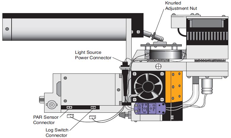
- Unhook the PAR sensor connector from the port on the side of the sensor head by gently pulling straight out. You will need to remove the tripod mounting bracket, if attached, to access the connector.
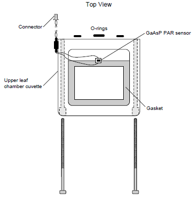
- Remove the upper half of the standard leaf chamber cuvette using the 3/32” hex key provided in the spare parts kit. The upper half of the leaf chamber is secured by two long screws that can be seen in front of the cuvette (Figure 1).
- Before installing the narrow leaf chamber, transfer (or install new) air pas- sage O-rings onto the upper leaf chamber cuvette. Lightly grease the O-rings with silicon lubricant.
- Remove the air hose from the underside of the leaf chamber, and remove the leaf temperature thermocouple by pulling it out of the chamber bottom.
- Remove the two long screws from the lower half of the leaf chamber using the 3/32” hex key.
Installing the 6400-11
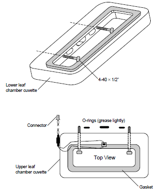
- Install the 6400-11 upper cuvette with two 4-40 × 1/2” screws included. Note that the screws are inserted from within the chamber cuvettes (Figure 2). Attach the PAR sensor connector as shown in Figure 3. Make sure the PAR sensor is attached to the connector near the rear of the analyzer housing, not to the log switch connector.
- Install the 6400-11 lower cuvette with the two 4-40 × 1/2” screws included. Make sure that the air passage O-rings are lightly greased and in place. Insert the leaf temperature thermocouple holder as shown in Figure 3.
- Reattach the air hose to the underside of the 6400-11.
Operational Considerations
When using the 6400-07 or 6400-11 chambers, there are a number of configuration issues that must be addressed. What follows is an explanation of what these are, followed by some guides to implementing an appropriate configuration. This needs to be done only once, as you will have constructed a configuration file that can be selected at power up to match whatever chamber you are using.
Boundary Layer Conductance
The LI-6400 normally computes boundary layer conductance based on leaf area, fan speed, and a lookup table that is appropriate for broadleaves in the 2 × 3 cm standard chamber. When measuring needles, or when using another chamber, this lookup table should not be used.
2 × 6 cm chambers: When measuring broadleaves in one of the 2 × 6 cm chambers (6400-07 or 6400-11), the “BLCond=” configura- tion parameter should be set to the file name “/Sys/Lib/BLCTable_2x6” (you’ll have to add this file if you don’t have OPEN V2.5 or above).
Conifers: Since conifer needles have much higher boundary layer conductances than broadleaves, and typically low stomatal conduc- tances, it is usually sufficient to use a fixed, rough estimate for this boundary layer conductance. A value of 4 or 5 mol/m2/s is not unreasonable (Landsberg and Ludlow, 1969). This change is made in the Config Editor, using the item “BLCond=”. Normally, what follows is the file specifier for the lookup table (such as “/Sys/Lib/BLCTable_2x6”, or the factory default “/Sys/Lib/StdBLCTable”), but a fixed value can be substituted for a file name.
Light Sensor
The configuration parameter “CalPARGaAs=” determines the calibration factor for the in-chamber light sensor, and should be set to match the specific chamber top in use. In addition, the “LightSource=” parameter should be set to match (as closely as possible) the light source from the menu provided, such as “Sun+Sky”.
Leaf Temperature Measurement (6400-07)
The leaf temperature is not measured directly when using the clear-bottomed 6400-07 chamber. The thermocouple which is normally used for that purpose is instead used to measure the temperature of the air exiting the chamber, and leaf temperature comes from an energy balance computation. (Refer to LI-6400 Technical Note 5 for more details on the leaf energy balance assumptions and implementation.)
Setup
The _Optional Installer (introduced with OPEN 2.5), makes setting up a configuration file for using the 6400-07 or 6400-11 chambers quite simple. If you have a prior version of OPEN, you might want to install OPEN 2.5 and save yourself some work.
OPEN 2.5 or higher:
- Access the “_Option Installer” in the Config Menu.
- Select “Show Status” (f1). See if the 2 × 6 chamber top is in your unit’s calibration list. It will have a GB-nnn serial number. If it is not there, select “Add Item” (f2) and enter the light sensor’s calibration data from the calibration sheet.
- To generate a configuration file for the 6400-07 or 6400-11, select “Make Config” (f3).
- Select “6400-07 2x6 Clear Bottom” or “6400-11 2x6 Opaque Bottom”.
- Select the appropriate GB-nnn chamber top from the list.
- (If you selected the 6400-11 above, you will be asked “Leaf Temperature: Measured or Energy Balance ? (M/E)”. Press M or E. (‘M’ assumes that you will have the thermocouple in contact with the leaf material, and ‘E’ assumes that the thermo- couple will be measuring the air temperature in the chamber).
- For “Leaf Type: Needles or Broadleaves ? (N/B)”, press N or B.
- You will be shown the generated configuration. Press <esc> to exit this view.
- “Store This Configuration?” Press Y if you wish to store this, and you will be given a default file name, based on what the configuration is, and an opportunity to modify the name.
- Select “Exit” (f5) to exit the _Option Installer program.
You are done. The rest of the instructions are how to do this without using the _Option Installer.
OPEN versions prior to 2.5:
Step-By-Step #1 (Hopefully only necessary if you purchased the chamber after your original LI-6400 order). This step-by-step does two things, all from the Filer; it checks to see if the boundary layer conductance lookup table is in place, and it checks to see if the calibration for the light sensor is in place.
- Access the Filer, press D (directory select), and select the directory “/Sys/Lib”. See if the file “BLCTable_2x6” is present. If it is, go to step 6.
- Tag the file “StdBLCTable”, and press U (to Duplicate the file). A file named “StdBLCTable copy” will be created.
- Put the cursor on the file “StdBLCTable copy” and press R (to rename). Name the file “BLCTable_2x6”.
- Put the cursor on the file “BLCTable_2x6” and press E (to edit). Make the file look like the following (note that everything before the BLCTABLE= line is just comment, and is not important. For details on the format of this file, see LI-6400 Technical Note 15):
2x6 chamber, broadleaves. 7/26/96 BLCTABLE= 2.0 12.0
0.1 0.1
1.2 0.6
1.6 0.9
1.9 1.1
2.2 1.4
2.4 1.5
- Press <esc>, then U (to update), then Q (to quit).
- In the Filer, press D (directory select), and select the directory “/Sys”.
- Put the cursor on the file “Calibration”, and press E (to edit). See if there is an entry in this file that matches your 2 × 6 cm chamber top’s serial number. This will be a number such as GB-0113. Toward the end of the file, you should see something like
...
CalPress = 89.123 0.005522
CalParGaAs= 0.76 // GA-295 11 Apr 1996
// CalParGaAs= 0.73 // GB-113 2 May 1996 <- the line in question
CalParOut= 4.77 // Q21926 15 Apr 1996
...
where the calibration value (0.73 in the example above) and serial number (GB-113) matches the one on your calibration sheet. If there is no such entry, add one using the information on the calibration sheet. The line should begin with two slashes and a space before the CalParGaAs=.
- If you added the calibration line in Step 7, press <esc> then U, to update the file, then Q. Otherwise, just press <esc> then Q.
- Press <esc> to exit the Filer.
Step-By-Step #2. This builds a configuration file for the chamber.
- From OPEN’s main screen, access the Config Menu, then the Config Editor.
- Press the Add function key, and add the calibration entry for your chamber top (the CalParGaAs= with the appropriate serial number)
- If there is no item “BLCCond=”, press the Add function key, and add it.
- With the cursor on the “// CalParGaAs=” line that was added in step 2, remove the “// “ at the start of the line by pressing the Labels key, followed by the “Enable” function key. If there are other CalParGaAs= entries in this configuration file, disable them (add “// “ prefix) using the “Disable” function key.
- Put the cursor in the “BLCCond=” item, and press the Edit function key (you may have to press the labels key first). If you are measuring conifers, set it to
BLCCond= 5
If you are measuring broadleaves, set it to
BLCCond= “/Sys/Lib/BLCTable_2x6”
Hint: You can add two BLCCond= items, and set one for conifers and one for broadleaves, then use the Enable and Disable function keys to easily change from one to the other:
...
// BLCCond= 5 // conifers
BLCCond= “/Sys/Lib/BLCTable_2x6” // broadleaves
...
- You may want to set the STOMRAT= and AREA= items to an appropriate default values. If you will be filling the 2 × 6 aperture with a broadleaf, then 12 is a good choice for AREA=.
- Store the configuration under a new name by pressing the “StoreAs” function key (you may have to press the labels key first).
Name the file something appropriate, like “2x6 chamber broadleaf”, or “2x6 needles, No T/C”.
(If you are using the 6400-11, and measuring the leaf temperature with a thermocouple, you are done. Go to step 10. Otherwise, continue on to set up for energy balance computations).
- Edit the item “ComputeList=”, and select the file “Clear Bottom EB” in (/Users/Configs/Comps). (If this file does not exist, select the file “Default Using EB” instead).
- Edit the item “Displays=”, and select the file “Std+EBTleaf” in (/Users/Configs/Displays).
- Edit the item “LogFormat=”, and select the file “Std+EB” in (/Users/Configs/LogFormat).
- Exit the Config Editor by pressing the OK function key (if you want to implement this configuration now), or the cancel function key if you don’t.
Note: If you made a typing error in the boundary layer conductance table file name, or if the file does not exist, the message “Cannot Open File” will appear each time the configuration file is implemented.
Clear Bottom Chamber Irradiance Consideration
If the file “Clear Bottom EB” was not available for step 7 above, then read this section and follow the steps at the end.
Light Measurement. Once you have implemented an energy balance computation for leaf temperature, you may want to account for the “extra” radiation incident on the leaf’s bottom. The standard energy balance compute list “Default Using EB” only accounts for the top incident radiation: the variable EBdT (leaf-air temp difference computed from energy balance) is computed by a call to function EB_DeltaT() (see page 5-7, LI-6400 Technical Note #5):
EB_DeltaT( parIn_um * alphaK, tCham_c, tLeaf_C, condBL_one, #20)
The first parameter passed to this function is the absorbed radiation estimate, computed from the incident quantum flux (parIn_um) multiplied by a factor that converts μmol/m2/s to absorbed W/m2 (alphaK). One method of accounting for incident radiation on the bottom of the leaf is to mount the external quantum sensor to view downward, rather than upward. The EBdT variable would then become
EB_DeltaT( (parIn_um + parOut_um)* alphaK, tCham_c, tLeaf_C, condBL_one, #20).
Alternatively, one could assume that a fixed fraction of the downward radiation were coming up from below. For example, if you assumed the bottom flux to be 20% of the top:
EB_DeltaT( parIn_um * 1.2 * alphaK, tCham_c, tLeaf_C, condBL_one, #20).
If you choose to make a change in how EBdT is computed, make the change as follows:
- Access OPEN’s Config Menu
- Select “User Compute List Editor”
- Make the changes.
- Press <esc>, then S (to save as a new file name). Name it “Clear Bottom EB”.
- Press Q to quit. When asked if you wish to implement this change, press Y. The compute list is then compiled. If there are errors, they are reported. You should then re-edit the ComputeList, fix your mistakes, and press <esc>, then U to update the file.
- Since you changed ComputeList file names in step 4, you need to update the stored version of the Config file (the ComputeList= name has changed). Simply select the Config Editor, press OK, and your file “Std Clear Bottom Chamber” will be updated.