
Printable PDF: Scrubber/Desiccant Tube Assembly Tubing Replacement
This content as a pdf that can be saved to your computer or printed.
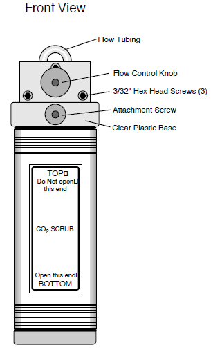
The soda lime and desiccant tubes can be disassembled if necessary, to clear the air passages, or to replace the small flow tubing should they become pinched or clogged with debris.
What you’ll need: 3/32” and 5/32” hex keys, channel lock pliers, and 1/16” I.D., 1/8” O.D. polyurethane tubing.
To disassemble and service a chemical tube flow adjustment assembly, follow these instructions.
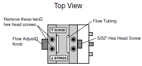
- Set the flow adjust knob midway between SCRUB and BYPASS (Figure 1‑3).
- Remove the flow adjust knob (Figure 1‑1).
- Figure 1‑1. Remove the flow adjust knob with a 5/32” hex key and a pair of pliers.
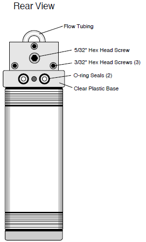
- Figure 1‑2. Remove the three hex head screws on the rear of the assembly.
- Note: This knob must be oriented in the same way when re-assembling; mark the outer face before removing.
- Use a 5/32" hex key to hold the 5/32” hex nut on the rear of the assembly (Figure 1‑3), and grip the flow adjust knob with a pair of channel lock pliers. Turn the knob counterclockwise (toward SCRUB) to loosen. Remove the knob and the white washer that is beneath it.
- Figure 1‑3. Remove the two screws nearest the front of the assembly.
- Use a 3/32" hex key to remove the three screws on the front and rear of the assembly, and two of the four screws on the top. Leave the top two screws nearest the side with the flow adjust cap nut (opposite the side where the flow adjust knob was removed).
- Use a knife to peel up one end of the SCRUB and BYPASS stickers. The front and middle pieces of the assembly can now be removed to expose the flow tubing (Figure 1‑4).
- Figure 1‑4. Inspect the tubing, hose barbs, and air passages. Replace tubing if necessary.
- Inspect the air passages and the flow tubing.
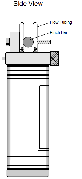
- Note the brass pinch bar in between the two pieces of tubing. When the flow adjust knob is turned, this bar moves backward or forward to pinch off one or the other of the two small air tubes. If this tubing remains compressed long enough (especially in hot weather) it can seal closed. If that appears to be the case, replace the tubing.
- Pull up on the tubing to free it from the small hose barbs. You may need to unthread the pinch bar to get at the tubing nearest the rear of the assembly. Cut a 2 3/4" (7 cm) piece of 1/16" I.D., 1/8" O.D. polyurethane tubing, and reattach to the hose barbs.
- Inspect the hose barbs and the small air passages in the clear plastic base of the assembly for any debris that might be lodged there. Blow air through the passages if necessary to clear debris.
- Reassemble.
- Reverse the above procedure. When it is time to reattach the flow adjust knob, make sure to put the white washer on first, and be sure the knob is oriented correctly. If you did not mark the face of the knob in Step 2 above, look at both sides of the knob; there is a set screw threaded into the knob. The side of the knob which accepts a 3/32" hex key is the side that should face away from the flow control assembly.