
Printable PDF: 200 mHz Digital Board Upgrade
Instructions for installing the 200 mHz digital board.
Before You Begin
The LI-6400’s digital board contains, among other things, some instrument specific calibration files. Therefore, before changing digital boards, it is necessary to download these from the old board, and then upload them onto the new board once it is installed. In addition, you may have data or configuration files that you want transferred from the old memory board to the new one. Do the following steps to accomplish these transfers:
Windows Instructions
- Install the LI-6400 File Exchange V2.0 program.
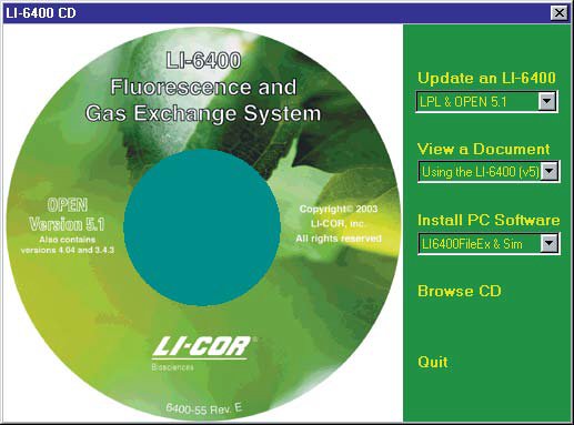
- Place the 6400-55 CD of Version 5.1 in your PC. If it is not there already, select “LI6400FileEx & Sim” in the drop-down menu under Install PC Software (Figure 1‑1). Then click on “Install PC Software”.
- Connect the LI-6400 to a PC
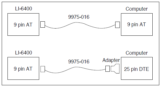
- This requires the 9975-016 cable that is shipped with the LI-6400 (Figure 1‑2).
- Put the LI-6400 into File Exchange mode
- From power on, press escape when asked if the chamber/IRGA is connected. This will get you to the LPL screen. Then press X to enter file exchange mode.
- Run FileEx
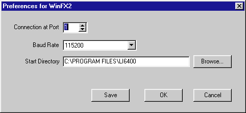
- You can launch it from Start Menu, Programs. If the LI-6400 is connected to COM1 on your computer, communication between the LI-6400 and the computer will be established automatically. If the instrument is connected to a different serial port, go to the File Menu, select Prefs, and choose the correct communication port.
-
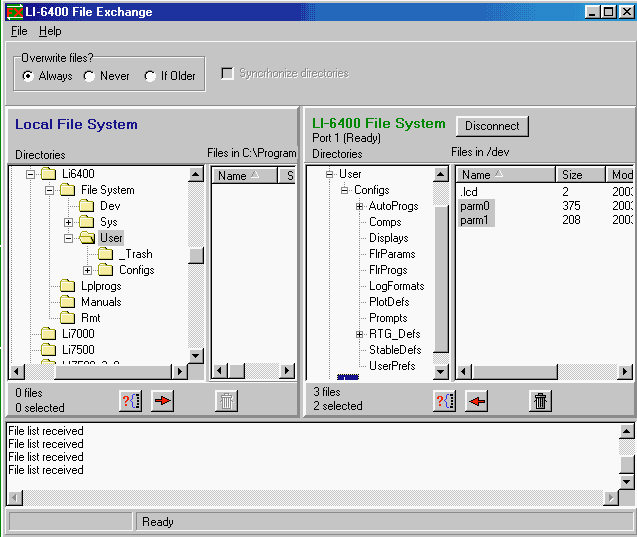
- Transfer the calibration files
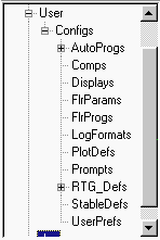
- The calibration files /dev/parm0 and /dev/parm1 do not appear in the normal file system, but they are accessible via the File Exchange directory listing, as shown in Figure 1‑3.
- Locate the User/dev directory in the LI-6400 File System window and highlight parm0 and parm1.
- Choose a directory on the computer to which these files will be sent, and click on the left arrow button below the LI-6400 File System window to move the parm0 and parm1 files.
- Save any data files you might need
- Open the User directory on the LI-6400, and copy any data files you might want, if you haven’t done this already. Once you pull the board from the LI-6400, you will not be able to retrieve these files without re-installing the board.
- Save any configuration files you might need
- Most of the configuration related files are already on the new digital board. However, if you have some custom configuration files (favorite displays, custom autoprograms, etc.) you may want to copy them from the old board, and install them on the new board.
-
Note: Don’t bother copying files in the StripDefs directory; they will be ignored if you put them on the new digital board. The real time graphics on the new board are different.
Macintosh Instructions
- Install FX/Mac version 1.6 or later
- Place the 6400-55 CD of Version 5.1 in your Macintosh. Locate and run the installer for FX/Mac.
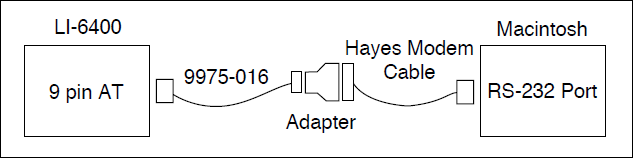
- Connect the Mac to the LI-6400
- This requires the 9975-016 cable that is shipped with the LI-6400 (Figure 1‑4), and a Hayes Modem Cable (not included).
- Put the LI-6400 into File Exchange mode
- From power on, press escape when asked if the chamber/IRGA is connected. This will get you to the LPL screen. Then press X to enter file exchange mode.
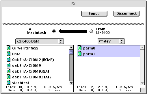
- Run FX/Mac
- With FX/Mac version 1.6, the normally hidden /dev directory will appear in the root, along with /User and /Sys. Open that directory, and copy parm0 and parm1 to your computer.
- Copy any other data or config files.
See notes under the Windows section, steps 6 and 7.
Disassembly and Reassembly
- Power the LI-6400 off, and disconnect all cables and batteries
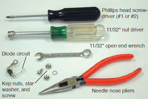
- Assemble the tools shown below; be sure to use the disposable grounding wrist strap (not pictured) before opening the LI-6400 console case or beginning the installation procedure.
- Remove the console bottom shell
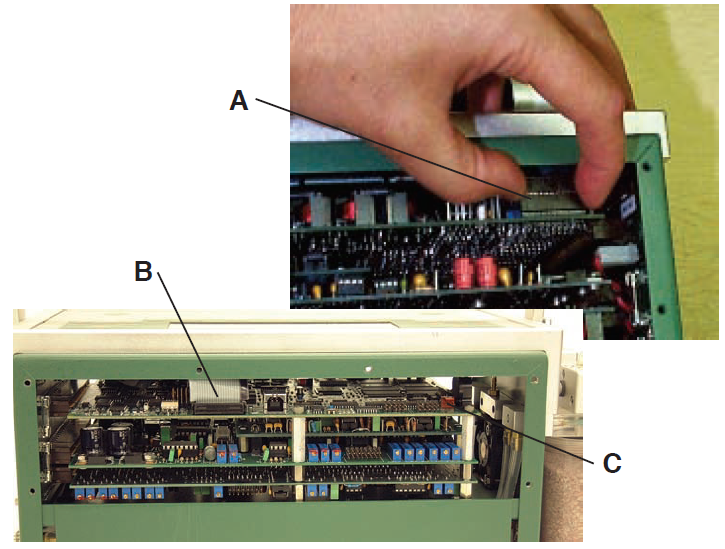
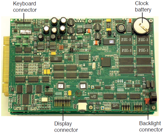
- Unplug the display and keyboard connectors
- Unplug the keyboard connector by carefully lifting it up from the pins on which it sits (A in Figure 1‑6). Then, unplug the display connector on the other side of the console (B). Finally, if there is one, unplug the back light connector (C).
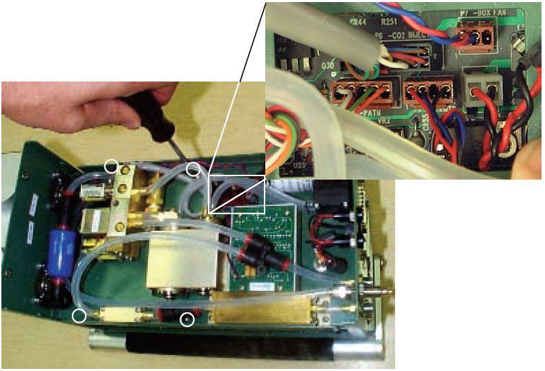
- Turn the console upside down and disconnect all flow board connectors
- All of the connectors in question go through a square hole to the flow board (Figure 1‑7).
- Remove the board assembly retaining screws
- There are 4 shown by the white circles in Figure 1‑7.
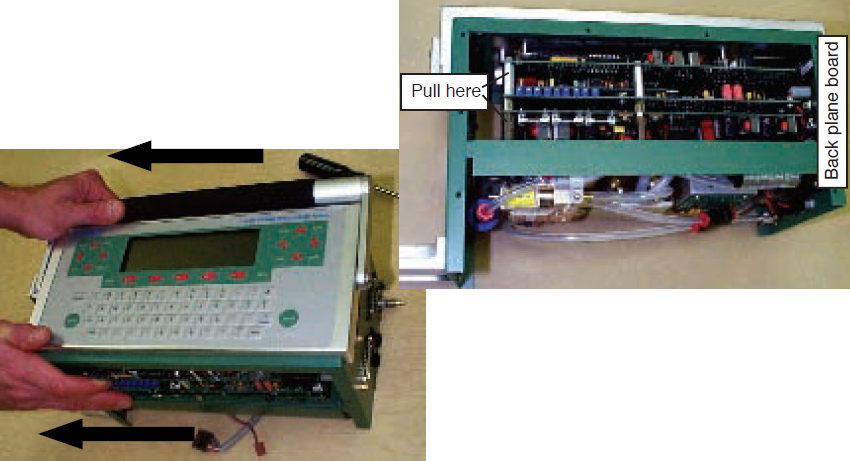
- Unplug the board assembly
- All of the boards in the assembly connect to the back plane board at the right end of the console. Unplug these boards by hooking your fingers on the standoffs on the back of the assembly and pulling (and rocking back and forth gently) the assembly out of the connectors (Figure 1‑8).
- Slide the board assembly out of the console
- Be careful that the display and keyboard cable and connectors don’t snag on the boards as you slide them out of the console.
- Remove the clock battery (Figure 1‑9).
- Pry the clock battery from its holder and re-install into the new board before going on to the next step.
- Install the new CPU board back in the board assembly.
Re-installing the PC Boards
- Slide the new board assembly back into the console
- Be careful not to snag the keyboard and display connectors and cables.
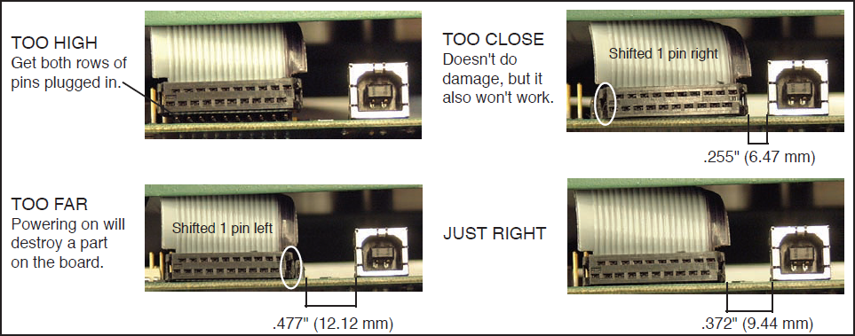
- Re-connect the keyboard, display, and backlight (if present) connectors
- Make sure the connectors are centered, especially the display connector (Figure 1‑10). If you are off a pin to the left or right, you can do damage when you turn on the power. Note the distances shown below between the display connector and the small connector adjacent to it on the right; the proper distance should be .372" (9.44 mm).
- Re-seat the board assembly
- Line up the edge connectors of the three boards, and push them into the back plane board by pushing on the standoffs between the boards.
- Install the retaining screws
- Turn the console over, and re-install the four screws. The board assembly has to be fully seated before the screw holes line up.
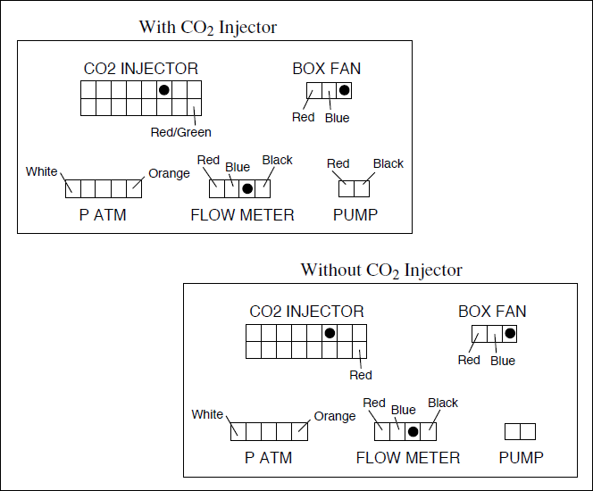
- Reconnect the flow board connectors
- Refer to Figure 1‑11. Note the labels on the flow board by each connector.
Install the Diode Assembly
The diode assembly is required with the new digital board for signal noise suppression. Follow these steps to install the diodes:
- The diode circuit will be installed on the underside of the card cage, nearest the right side of the console that contains the power and sensor head connections. It is installed between the ground lug on the LI-6400 case and the black wiring attached to the negative power input.
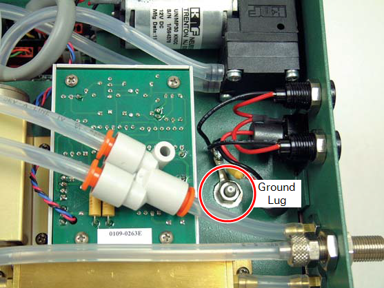
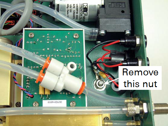
- Use the 11/32" nut driver (or equivalent) to remove the nut from the ground lug, as shown below. This nut will not be reinstalled; a kep nut included will be installed in its place.
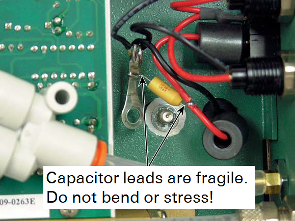
- Carefully remove the ring terminal from the ground lug and move the terminal away from the lug slightly, as shown. IMPORTANT: the wire leads on the capacitor are fragile and can break easily. Do not bend these leads back and forth or stress them in any other manner. Leave the star washer on the ground lug.
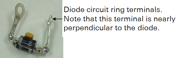
- Note the position of the ring terminals on the diode circuit. One of the terminals should be nearly perpendicular to the diode, while the other is angled slightly; the ring terminal that is perpendicular to the diode is installed on the ground lug, and the other terminal is mated to the existing ring terminal on the capacitor. These ring terminals on the diode circuit can be bent slightly if needed to facilitate mating to the capacitor.
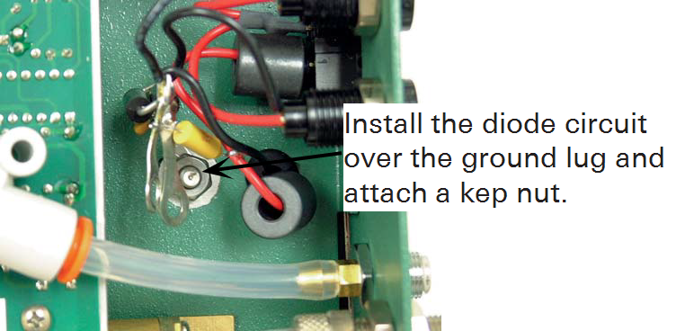
- Install the diode circuit over the ground lug, on top of the existing star washer. Install a kep nut onto the ground lug to secure the diode circuit. Hold the diode circuit in place and tighten the kep nut using the 11/32" nut driver.
- Use the needle nose pliers to carefully bend the diode circuit's top ring terminal to match the angle of the battery ground's ring terminal, so that the two can be mated with the screw. Again, be careful not to stress the capacitor leads on the battery ground's circuit. Install the supplied screw through the two ring terminals; use a star washer between the ring terminals, as shown. It may be helpful to hold the star washer with the needle nose pliers while performing this step.
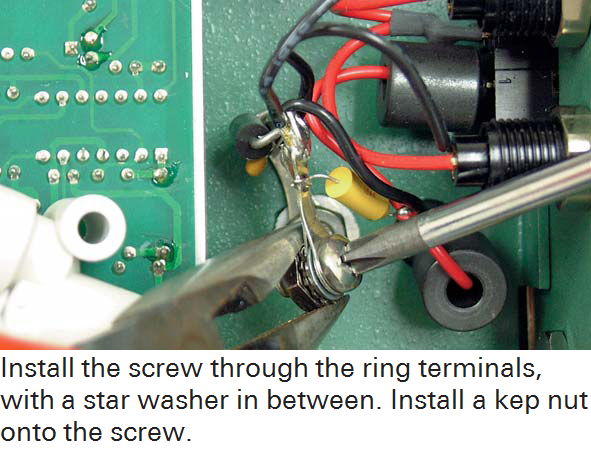
- Install a kep nut onto the screw. Hold the kep nut with the needle nose pliers while turning the screw.
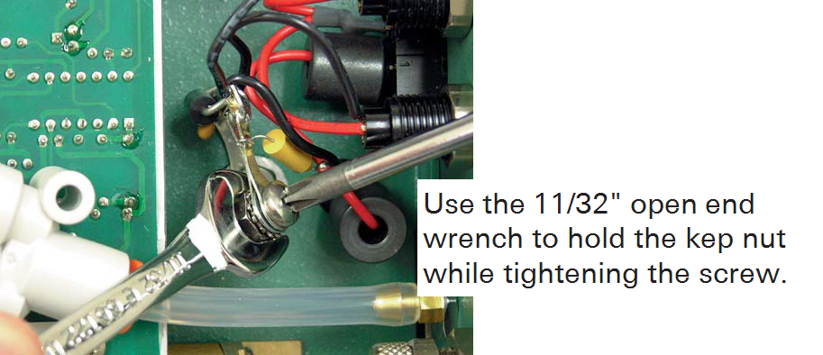
- Use the 11/32" open end wrench to hold the kep nut, and tighten the screw.
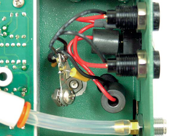
- Final visual inspection. Make sure that there is plenty of clearance between the newly installed diode circuit and any other components; the wiring must not touch anything else.
- Reassemble the LI-6400 console.
Re-install Files
Windows:
- Run File Exchange.
- On LI-6400, open /dev directory.
- On local disk, locate the parm0 and parm1 files saved earlier.
- Copy those files to /dev.
- Copy any data or configuration files you may want.
Macintosh:
- Run MacFX.
- Connect with LI-6400.
- Open /dev directory on LI-6400
- Locate parm0 and parm1 files on local disk.
- Copy them to /dev.
- Copy any data or configuration files you may want.