
Printable PDF: Flow Restrictor Field Kit
Instructions for the CO2 6400-928 flow restrictor kit.
Installation Instructions for the LI-6400 Portable Photosynthesis System
There is a small amount of residual oil inside the CO2 cylinders used with the 6400-01 CO2 Injector. If the oil filters are not replaced on a regular basis, the oil can enter the flow path via the copper supply tube and clog the flow restrictor. During operation of the CO2 injector, if you are unable to attain high enough CO2 levels (>2000 ppm), or if the CO2 takes more than 3 minutes to stabilize at the upper limit during mixer calibration, and you are using a fresh CO2 cylinder and oil filter, it may indicate that the flow restrictor is clogged.
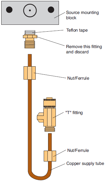
The flow restrictor must be replaced if it becomes clogged. The restrictor is pressed into the fitting connected to the top of the copper supply tube, and can not be removed; you must replace the entire fitting. A kit is available (part #6400-928) that includes a fitting with the new restrictor, nuts with integral ferrules, and copper supply tube.
To replace the flow restrictor assembly:
- Place the source mounting block into a vise.
- Loosen the nut at the base of the “T” fitting.
- Loosen the other nut at the top of the copper supply tube, and discard the supply tube, nuts, and attached ferrules.
- Remove the fitting containing the flow restrictor and discard. Install the new fitting/restrictor.
- Note that the fitting is wrapped at one end with Teflon tape. Insert this end into the source mounting block and tighten securely.
- There are 2 nuts in the kit that have ferrules preinstalled. Insert the short end of the copper supply tube up through the bottom of the nut (opposite the threaded end). Insert the long end of the copper supply tube up through the nut and into the flow restrictor fitting. Push the short end of the copper supply tube up into the “T” fitting as far as it will go, and tighten the nut (tighten only a few turns; don’t overtighten). Tighten the nut on the flow restrictor until it stops.
You may choose to test the injector for leaks after finishing the flow restrictor installation, as follows:
Remove the source from the side of the console and install a fresh cartridge. Dip the source regulator assembly into a clear beaker of water, and look for bubbles. Dip it only as far as the bottom of the aluminum block that the mounting screws pass through. (Do not dip it any deeper because water should be kept away from the hole where CO2 exits the source. There is a flow restrictor behind this hole, and if it gets wet, it won’t work again.) The most probable source of a leak is one of the two compression fittings on the copper tubing that goes from the regulator body to the mounting block. If that is the case, tighten the nut on the copper tubing 1/8 turn at a time until the leak stops. The leak could also be at the cap on the “T” fitting which contains the filter. If this is the case, and tightening the cap doesn’t help, check the O-ring in the cap. It may be torn.
When you remove the source from its bath, do not turn it upside down while it is wet. This will prevent water from running into the regulator through the large hole on its bottom. Dry the bottom of the source and the inside of that hole with an absorbent towel before turning it over.