
Printable PDF: Using the Whole Plant Arabidopsis Chamber
This content as a pdf that can be saved to your computer or printed.
Summary
- The Whole Plant Arabidopsis (WPA) Chamber measures whole plant CO2 exchange.
- Rosette photosynthesis can be isolated using a clay cap and a slight overpressurizing of the chamber.
- Effective for healthy Arabidopsis plants larger than 1.5 cm2 total leaf area.
- Only rosette-level parameters should be examined (e.g., rosette transpiration instead of leaf transpiration).
- Environmental conditions in the WPA Chamber should be chosen in relation to growth conditions.
Arabidopsis and Photosynthesis
Advances in molecular and genomic techniques in plant biology have provided researchers with diverse tools to study metabolic and photosynthetic processes in plants. The genome of Arabidopsis thaliana is among the most widely studied of all plant species. With the wealth of genetic information and tools available, studies of the genetic basis of physiological pathways can now be undertaken with greater ease. The 6400-17 Whole Plant Arabidopsis (WPA) Chamber provides scientists with a novel tool for exploring photosynthetic capacity, respiration rates and other gas exchange parameters among mutant collections of A. thaliana and other short-stature species.
Gas exchange studies of small rosette plants have been limited because leaves with short petioles are difficult to enclose within a clamp-style chamber and because small leaf areas lead to large uncertainties in gas exchange measurements. The WPA Chamber circumvents these issues by enclosing the entire rosette within the chamber, thereby alleviating the need for narrow approach angles and increasing the total leaf area that can be assessed. However, by enclosing the whole plant and container, net CO2 flux is the combination of rosette photosynthesis, plant respiration, plant growth medium flux and container sorption. In some studies, this approach is exactly what is desired, such as assessments of net plant carbon exchange (net CO2 uptake = photosynthetic uptake – all respiratory losses). If researchers are interested in photosynthetic capacity alone, then the rosette must be isolated.
When examining isolated rosette gas exchange, care should be taken to differentiate between canopy level and leaf level processes. To illustrate, stomatal conductance (gs) is not calculated by the LI-6400XT when the WPA Chamber is installed because the rosette structure makes an assessment of leaf boundary layer conductance nearly impossible. The low-lying leaves of a rosette slow air movement around each leaf, thereby increasing the boundary layer (the calm air layer around each leaf). The rosette also slows air movement over the plant, creating a second layer of still air over the entire plant. To calculate gs, the boundary layer conductance is assumed to be very high (i.e., not limiting), allowing it to be considered negligible in the calculation of total resistance to evapotranspiration (see LI-6400XT Manual, Chapter 1 for a complete description). However, since the total water lost by the plant is measured, an assessment of canopy transpiration can be made. In most instances, canopy level parameters are measured with the WPA Chamber, rather than leaf level parameters.
Plant culture practices – Separating rosette and planting medium flux
In many research settings, Arabidopsis is cultured in small containers filled with a peat-based planting medium that is kept at or near water saturation. These plants are grown indoors in greenhouses or in growth cabinets with low light levels (many growth cabinets are < 200 µmol m-2 s-1, approximately 10% full sunlight). The combination of these conditions can lead to bacterial and/or algal growth in the planting medium. While not necessarily detrimental to the plant, this does have an impact on CO2 flux. Therefore, it is important to have a method of isolating the CO2 flux from the planting growth medium.
We have developed several methods to suppress CO2 flux from the plant growth medium for the 6400-17 WPA Chamber. These methods can be used individually to block much of the CO2 flux, or in combination to ensure that there is no flux from the planting medium.
Plant Culture
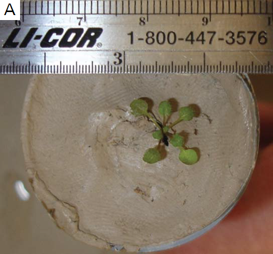
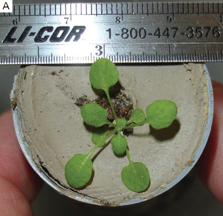
Arabidopsis must be grown in either 4 cm diameter Cone-tainers™ or 6.5 cm diameter pots for use in the WPA Chamber. Once the planting medium is in the container, the surface of the medium can be sealed by several gas-tight methods. The preferred method is to use standard pottery clay to create a 4 - 6 mm thick layer on top of the medium that adheres to the containers’ sidewalls. A 5 - 8 mm hole is made in the center of the clay disk through which either seeds can be planted or 5 - 10 day old seedlings can be transplanted from agar plates or planting medium (Figure 1‑1; A). As long as the planting medium remains moist, the clay will also and will provide a good germination and growth surface for the young plants. As the plant grows, it will occlude the hole, suppressing any CO2 flux through the planting medium.
A slightly messier alternative is to spread petroleum jelly across the surface of the planting medium. This is also quite effective at blocking CO2 influx from the medium, but is more difficult to work with in general. From testing, we found that plastic film was not a suitable alternative because plants tended to germinate underneath the film. Additionally, plastic film did not seal around the plant as well since the hole size has to be cut to accommodate mature plants. This hole acted as a venturi and drew CO2 from the plant medium at higher rates than just the medium alone.
Exhaust Flow Restrictions
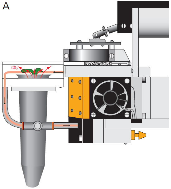
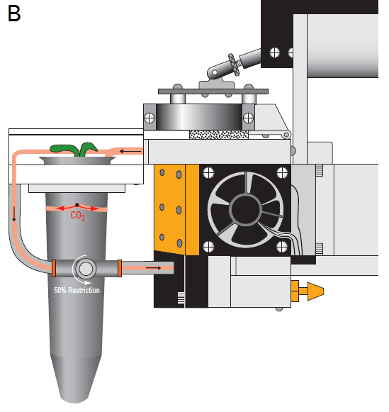
The LI-6400XT is an open, flow-through system where environmentally conditioned air enters the chamber, forcing an equal volume out the exhaust path. The WPA Chamber incorporates a flow-restricting needle valve (Adjustable Exhaust Tube Assembly, LI-COR part number 9964-118) into this path that allows the user to adjust the flow through the exhaust (Figure 1‑2). By restricting the exhaust flow, air is forced through the plant medium, which suppresses CO2 flux from the medium. Typically, closing the needle valve to 25 to 50% is sufficient to divert 100 – 150 µmol s-1 of flow through the medium, while maintaining enough flow through the match valve to match the IRGAs.
Forcing air to flow through the medium can increase pressure within the chamber due to resistance to flow through the plant growth medium. To prevent excessive overpressure within the WPA chamber, the user should perforate the container with one or two 0.3 mm holes located 1.5 – 2 cm below the top of the container (Figure 1‑2; B). Standard push-pins for bulletin boards work well for this purpose. These holes function as exhaust paths and reduce the back pressure on the system because of the decreased path length through the plant medium. Matching the IRGAs will remove any small offset in CO2 and H2O measurements due to the slight pressure increase.
For plants that are not needed for seed production, additional tests or assays, the CO2 flux contributions from the plant growth medium and/or roots can be measured directly. To measure this CO2 flux, the Arabidopsis plant should be measured in the chamber without making any of the adjustments above (use the Unrestricted WPA Chamber Exhaust Tube, LI-COR part number 6564-287). Once all measurements of the plants photosynthetic/respiration rate are completed, the vegetative portion of the plant is removed and the remaining flux can be measured. This flux from the plant medium and roots is then subtracted from the total measured with the intact plant.
Gas exchange nuances – Getting the best measurements
The CO2 concentration in growth cabinets and greenhouses can be higher than current ambient conditions (385 µmol mol-1 in 2008), commonly ranging from 600 – 800 µmol mol-1 or more. Plants grown in elevated CO2 adapt by decreasing stomatal density and aperture, decreasing Rubisco content, increasing starch storage, and other physiological adaptations (Curtis and Wang, 1998; Medlyn et al., 1999; Ainsworth et al., 2002). Therefore, it is important to configure the LI-6400XT CO2 mixer to replicate the growth conditions to get the best measurement of plant CO2 assimilation and/or respiration.
To normalize values for differences in leaf size and number, most gas exchange parameters are reported per leaf area. For Arabidopsis rosettes, either photographic analysis or destructive leaf area measurements can be used. Precise, destructive measurements of Arabidopsis leaf area can be made using a leaf area meter such as the LI-3100C, which has a resolution of 0.1 mm2. Non-destructive measurements of leaf area can be conducted with the photographic method using software such as “ImageJ,” offered for free by the National Institute of Health (http://rsbweb.nih.gov/ij/). A uniform, white background behind the rosette increases the contrast for image analysis.
Experimental Validation – Protocol and Results
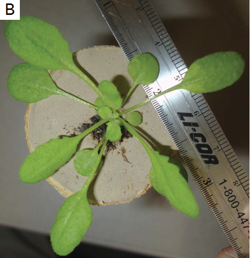
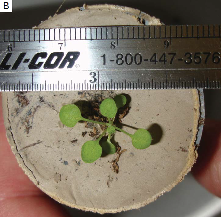
Validation of the WPA Chamber was made with both 4 cm Cone-tainers™ and 6.5 cm pots. Wild-type Arabidopsis (Col-0) was used in all tests involving plants. The plants were germinated on Miracle-Gro Potting Mix™ (forest compost, peat moss, perlite, wetting agent and 0.21-0.07-0.14 N-P-K) and transplanted 5 – 10 days post germination. The plants were grown under 175 µmol m-2 s-1 fluorescent light for 8- hour short days to prevent bolting. For most of the following experiments, 6 to 8 week old plants (5 – 7 cm rosette diameter, Figure 1‑1; B) were used.
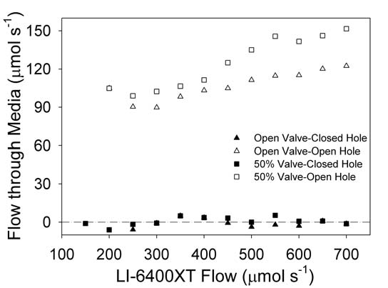
Mass flow out of the WPA Chamber through the medium was assessed with a precision variable area flow meter (FL-3803ST-NV, Omega Engineering Inc., Stanford, CT) placed in the chamber flow line. The flow meter was calibrated against a LI-6400XT mass flow sensor and pressure changes due to restrictions were measured by differential pressure sensor (DGM- 240169600, American Gage, Atlanta, GA). Air flow through the plant medium was calculated as the difference between inflow measured by the LI-6400XT mass flow meter and the outflow measured by the precision flow meter. For water-saturated peat (a common growth medium and also worst case scenario), there was essentially zero flow through the plant growth medium (Figure 1‑3, closed triangle).
When a needle valve in the exhaust path was closed to 50%, the flow through the medium remained 0 µmol s-1 (Figure 1‑3, closed square). However, when a small vent hole (~0.5 mm) was punched in the sidewall of the container about 2 cm below the top, the flow through the medium was 90 – 100 µmol s-1 (Figure 1‑3, open triangles). Closing the needle valve to 50%, further increased the flow through the medium to 100 - 150 µmol s-1 (Figure 1‑3, open squares). The amount of flow through the small vent hole will be dependent upon the plant growth medium type and the moisture content of the medium.
Plant root and microbial respiration plus diffusion though the plant growth medium causes an apparent CO2 flux into the WPA Chamber. Suppression of this flux is necessary to measure canopy-only CO2 flux. Different capping methods were explored including plastic film and heavy pottery clay. Containers of plant medium were incubated for 3 weeks alongside growing plants. The medium was then tested for effective barriers to CO2 flux into the chamber. Uncapped medium resulted in a 5.1 µmol mol-1 CO2 increase in the chamber (Table 1‑1). The influx of CO2 increased 5- fold when the container was placed into water to prevent diffusion through the medium out the bottom and was comparable to completely H2O-saturated medium. Covering the planting medium with plastic film (not shown) and a 4 mm-thick clay plug both suppressed CO2 flux into the WPA Chamber. When a hole was punched in either barrier to allow a plant to grow through, there was an increase in the CO2 flux into the chamber. However, later tests showed the growing plant more effectively filled the hole in the clay than the hole in the plastic film. Additionally, the plastic film was more difficult to secure to the container and was often torn during insertion into and removal from the WPA Chamber.
Suppression of CO2 flux from the plant growth medium was tested on media without plants and on media with 8-week old plants. The CO2 concentration inside the chamber was matched to the room CO2 concentration to remove any diffusion effects. Injections of 250 µl of pure CO2 were made 0.5 – 2 cm below the plant medium surface through small vent holes in containers. Vent holes > 1.5 cm below the top of the container were not as effective at suppression of the CO2 spike (ΔspikeCO2, data not shown). A second series of small vent holes were tested to assess aperture effects on the ΔspikeCO2 suppression. With greater plugging of the small vent hole, there were larger ΔspikeCO2 (Table 1‑2). For the least occluded vent hole (Restriction Level 1), the ΔspikeCO2 was similar to the negligible CO2 increase (0.1 µmol mol-1) when CO2-free air was injected into the plant growth medium. This is well within the specified IRGA peak-to- peak noise of 0.3 µmol mol-1 at 350 µmol mol-1.
The effect of the clay cap and flow through the plant growth medium is apparent in the trace of CO2 with the different techniques applied sequentially (Figure 1‑4). Without flow through the plant growth medium and/or clay cap on the medium, injection of pure CO2 resulted in a ΔspikeCO2 of 175 µmol mol-1 (Figure 1‑4, Event 2). The combination of a clay cap with 0.9 cm hole for the plant on the plant medium and/or forcing part of the exhaust flow through the medium completely suppressed CO2 flux into the WPA Chamber (Figure 1‑4, Events 4, 6, and 8).
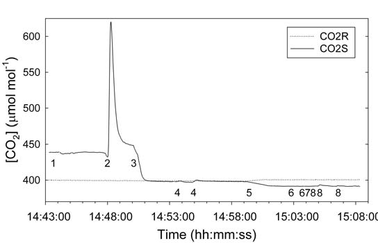
- All holes plugged and needle valve 25% restricted.
- Inject 250 µl pure CO2 (1x).
- Small vent hole in container opened.
- Inject 250 µl pure CO2 (2x).
- Paused program to place clay cap on surface of media.
- Inject 250 µl pure CO2 (2x).
- Small vent holes in container closed.
- Inject 250 µl pure CO2 (3x).
After 8 weeks of growth in short days, Arabidopsis plants completely occlude the hole in the clay cap. The plant rosettes were also large enough to cover the uncapped containers’ medium as well. The same pure-CO2 injection technique was used to test whether the larger rosette acted as a barrier to CO2 flux into the chamber. Plants that were grown in containers without the clay cap had the characteristic ΔspikeCO2 following an injection of CO2 into the plant growth medium (Table 1‑3). This spike was partially abated by restricting exhaust flow with the needle valve as seen in the previous experiments. When the rosette was removed, there was a slight increase in the ΔspikeCO2 suggesting that the rosette might suppress some of the CO2 flux, but the effect is small and large rosette size is not an effective way to reduce the influx of CO2 from the plant growth medium. The effectiveness of the clay cap was not improved by the large rosette covering the clay cap. As Arabidopsis plants grew, they occluded the hole in the clay cap, further restricting the CO2 flux from the plant growth medium.
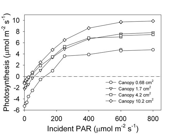
With the complete suppression of ΔspikeCO2 by clay capping and flow restriction, we tested the smallest measurable plant size. Arabidopsis plants of different sizes were measured over one week. Total plant leaf area was measured by photographing the plant and analyzing the image with ImageJ software (NIH, http://rsbweb.nih.gov/ij/). The smallest plant had 0.7 cm2 of leaf area (Figure 1‑5; B) and the largest had just over 10 cm2 (Figure 1‑1; B). Light response curves were measured for all plants (Figure 1‑6). The three larger-sized plants (1.7, 4.2, and 10.2 cm2) produced consistent photosynthetic responses to increasing light. Photosynthetic rates of 2 - 4 µmol CO2 mol-1 air at 100 to 200 µmol m-2 s-1 white light are comparable to previously reported rates (reviewed by Lake, 2004). The light compensation points for the entire rosette were 25 – 50 µmol m-2 s-1. Dark respiration rates are within reported ranges of 1 to 2 µmol m-2 s-1 (Byrd et. al., 1992). However, the smallest plant (0.7 cm2) was too small to produce consistent results. The ΔCO2 (0.6 µmol mol-1 between reference and sample IRGAs) that was generated by these small plants was only slightly larger than the IRGA precision, meaning that up to 50% of the measurement could be IRGA noise. (See LI-6400XT Manual, Chapter 1 for formula.) Larger rosettes take up more CO2 and thereby generate a larger ΔCO2 (2.5 µmol mol-1 for the 1.7 cm2 plant) which lessens the impact of IRGA precision on the measurement. Based on our results, rosettes of at least 1.5 cm2 are large enough to make light saturated measurements of photosynthesis. However, other factors can impact photosynthetic rates such as mutation, abiotic stress and growth conditions, and may necessitate greater leaf area of larger plants.
Conclusions
The WPA Chamber allows users to make rapid gas exchange measurements of either a whole plant or above-ground portion of Arabidopsis thaliana. Through a combination of cultural practices and instrument adjustment, CO2 flux from the plant growth medium and roots can be suppressed, allowing for direct measurement of the rosette gas exchange. Since the entire rosette is enclosed in the chamber, individual leaves are not measured and therefore care should be taken not to use specific leaf-level parameters, such as stomatal conductance or intercellular CO2 concentration. With careful selection and set-up of the environmental conditions in the chamber, accurate measurements of the Arabidopsis rosette can be made.
IMPORTANT NOTE: Although other sources for the following parts do exist, we recommend that you purchase directly from LI-COR, as many Cone-tainers and pots from other suppliers have similar specifications, but often do not fit our chambers.
LI-COR part number for the 1.5" diameter Cone-tainer: 610-09645
LI-COR part number for the 2.5" diameter pot: 610-09646
Bibliography
| 1 | Ainsworth, E.A., P.A. Davey, C.J. Bernacchi, O.C. Dermody, E.A. Heaton, D.J. Moore, P.B. Morgan, S.L. Naidu, H.Y. Ra, X-G. Zhu, P.S. Curtis and S.P. Long (2002). A meta-analysis of elevated [CO2] effects on soybean (Glycine max) physiology, growth and yield. Global Change Biology 8(8):1-15. |
| 2 | Byrd, G.T., R.F. Sage and R.H. Brown (1992). A comparison of dark respiration between C3 and C4 plants. Plant Physiology 100:191-198. Curtis, P.S., and X. Wang (1998). A meta-analysis of elevated CO2 effects on woody plant mass, form, and physiology. Oecologia 133:299-313. |
| 3 | Lake, J.A. (2004). Gas exchange: New challenges with Arabidopsis. New Phytologist 162:1-83. |
| 4 | Medlyn, B.E., F.W. Badeck, D.G.G. DePury, C.V.M. Barton, M. Broadmeadow, R. Ceulemans, P. DeAngelis, M. Forstreuter, M.E. Jach, S. Kellomäki, E. Laitat, M. Marek, S. Philippot, A. Rey, J. Strassemeyer, K. Laitinen, R. Liozon, B. Portier, R. Roberntz, K. Wang, and P.G. Jarvis (1999). Effects of elevated [CO2] on photosynthesis in European forest species: a metaanalysis of model parameters. Plant, Cell and Environment 22:1475-1495. |