Opaque Conifer Chamber (6400-22)
Printable PDF: Opaque Conifer Chamber installation instructions
Instructions for installing the 6400-22 Opaque Conifer Chamber onto the LI-6400/XT Portable Photosynthesis System.
Assembly Instructions
- Tools Required: #1 and #2 Phillips-head screwdriver; 5/64 and 3/32 inch Hex keys (included)
- Time Required: Approximately 30-45 minutes
Note: the sensor head handle must be removed to accommodate the OCC chamber, so a tripod is recommended for making measurements.
Removing the Standard Chamber, Handle and Chamber Manifold Plate
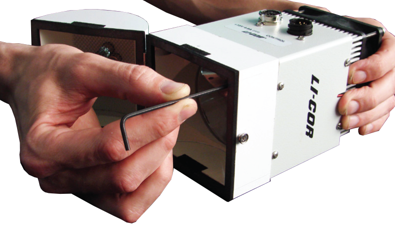
Remove the male end of the leaf temperature thermocouple connector by pulling straight out (Figure 1‑1). Remove the exhaust tube.
Disconnect the internal PAR sensor from the connector on the side of the sensor head by grasping the base of the plug and gently pulling straight out. If installed, the tripod mounting plate will need to be removed to access the connector (see LI-6400XT instruction manual).
Unplug the log button. If the log button wires are threaded underneath the bottom cover of the sensor head, this cover must be removed to free the log button connector.
With the handle open, unscrew the knurled leaf chamber adjustment nut until it is free of the handle (Figure 1‑1). Close and latch the handle. Wrap tape or a wire-tie around the handle so that it will not open. Failure to do so may result in the spring coming out.

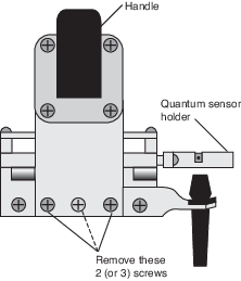
Remove the 2 (older units have 3) screws on the back side of the handle (Figure 1‑2) using a #1 Phillips head screwdriver.
Remove the upper half of the leaf chamber by removing the 2 remaining screws in the lower hinge plate. Use a 0.05 inch hex key (part #610-01463) to remove the external quantum sensor from its mount for use with the OCC if desired (see step 13). Disconnect the quantum BNC connector.
Remove the lower half of the leaf chamber and the sensor head manifold. Remove the 8 hex head cap screws (Figure 1‑3) with the 5/64 inch hex key (part #611-04311) to remove the lower leaf chamber and manifold. There is a thin vinyl gasket between the sensor head block and the manifold plate. Provided the gasket is clean and undamaged, save it for reuse in step 8.
Note: the screw nearest the leaf chamber forms a metal-to-metal seal in the air pathway and must be tight upon reassembly of the standard leaf chamber.
Installing the Opaque Conifer Chamber
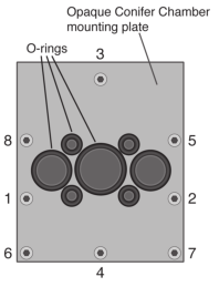
Reuse the vinyl gasket from step 7 or use a new one from the spares kit (part #6564-022). It should adhere to the optical bench, but if it becomes detached ensure that it is repositioned before attaching the new chamber mounting plate provided with the OCC. Attach the conifer chamber mounting plate with the 8 hex-head cap screws. Tighten the screws evenly in the cross-plate pattern shown in Figure 3. Repeat the tightening sequence. Caution: the screws are small and excessive force can break them.
Attach the lamp connector (Figure 1‑1) to the OCC mounting plate using one of the screws removed in Step 6.
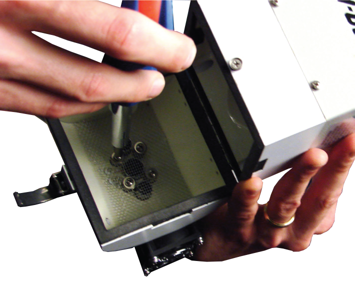
Ensure that all 7 O-rings (3 different sizes) are installed on the mounting plate, as shown in Figure 3. Install the screen and attach the chamber bottom to the mounting plate using the 4 screws and washers provided (Figure 1‑4, part #122-02218 and 167-00155 respectively). Tighten the screws evenly in a cross pattern (begin with the lower left screw, then the upper right, then the lower right, and finally, tighten the upper left). Repeat the tightening sequence.
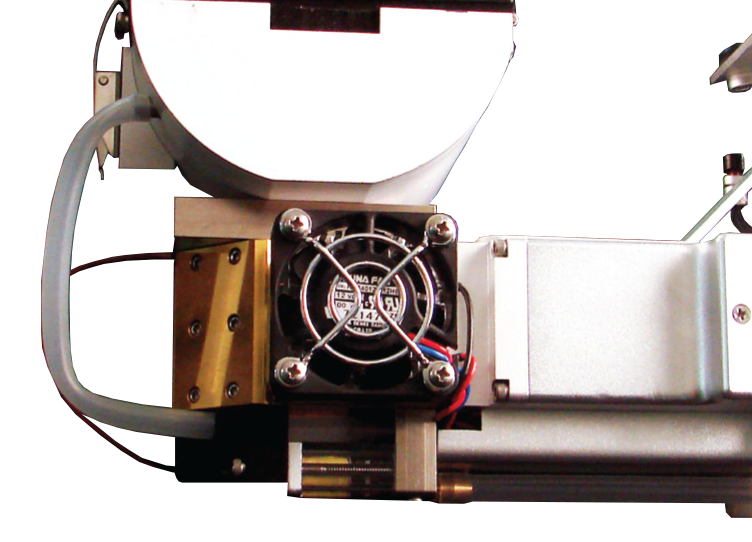
Connect the chamber air temperature thermocouple by pushing the purple connector straight into the connector on the IRGA head. Install either the standard OCC exhaust tube or the OCC exhaust tube with needle valve assembly (see Application Note #6 for a discussion of these configurations). It is easiest to first attach it to the metal tube on the sensor head and then to the metal tube on the chamber (Figure 1‑5).
If you are not using the RGB Light Source, attach the provided external quantum sensor mount (part #9816-020) to the upper chamber housing(above the hinge), using the 2 provided screws (part #122-00002). Secure the external quantum sensor (removed in step 6) in the mount with the provided thumbscrew (part #125-04975). Connect the quantum sensor cable to the BNC connector on the sensor head.
Installing the 6400-18/A RGB on the OCC
Remove the 4 screws on the bottom of the RGB light source using a #2 Phillips head screwdriver.
Perforate the clear plastic covering the 4 small holes on the top of the OCC. Ensure that the clear top of the OCC is not damaged over the large aperture since this will still be creating the air tight chamber seal.
Connect the 6400-18/A RGB to the top of the OCC with 4 hex cap screws (part #140-01633) using the 3/32 inch hex key (Figure 1‑6).
Connect power supply and control cables to the RGB. Connect the opposite end of the control cable to the 37-pin connector on the LI-6400XT console.
Close and latch the chamber.
Install the 6400-18/A RGB Support Bracket
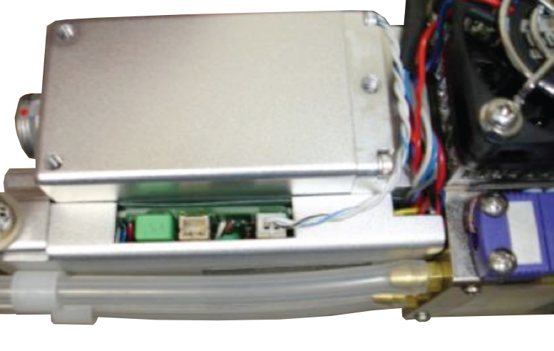
Connect the log button cable to the connector nearest the purple thermocouple connector (Figure 1‑7).
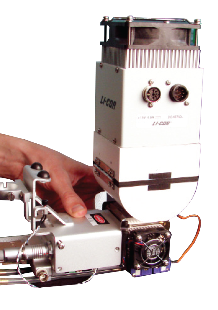
Attach the OCC support bracket to the sensor head with the 3 provided screws (part #122-00008) as shown in Figure 1‑8. If desired, the tripod mounting bracket can also be attached under the RGB support bracket.
Optional: Install the provided external quantum sensor mount (part #9816-020) to the support bracket with the screws (part #122-00002). Install the external quantum sensor in the mount with the included thumbscrew (part #125-04975) and connect the sensor cable to the BNC connector on the sensor head.
Software Configuration
The OCC requires that the LI-6400XT be operating version OPEN 6.1 or above. OPEN 6.1 can be installed on 200 MHz (previously OPEN 5.x) or 400 MHz (previously OPEN 6.x) digital boards. Older boards require a digital board upgrade; contact LI-COR regarding your system’s compatibility.
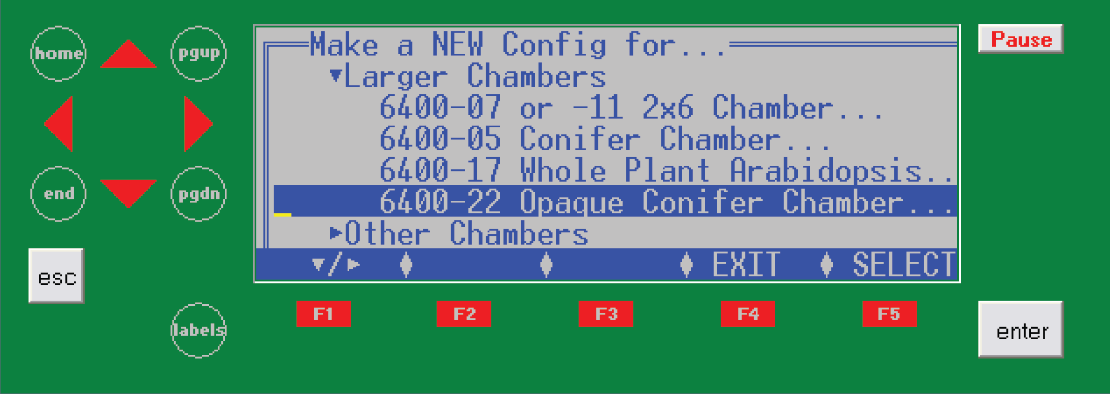
The OCC software is accessed in the Config Menu (f2). Select “New…”, and scroll to “Larger Chambers” and expand this list (▼/►). Select the “6400-22 Opaque Conifer Chamber” (Figure 1‑9). When prompted, select the desired light source (RGB) and then save as a new (N) configuration. See the LI-6400XT instruction manual, Chapter 16, for more information about configurations.