
This content as a pdf that can be saved to your computer or printed.
Summary
- Diffusion and bulk flow leaks occur in all chamber-based photosynthesis systems and can cause large errors on small photosynthetic and respiration rates.
- These leaks can be significant when chamber gas concentrations are different than the surrounding air (e.g. CO2 response curves).
- By employing exhaust restrictions to force air through the gaskets, a stable leak rate is established for the Opaque and Clear Conifer Chambers.
- Stable leak rates allow users to correct flux measurements for errors.
Diffusion and Bulk Flow Leaks Impact Photosynthesis
When making measurements of photosynthetic or respiration fluxes with chamber concentrations that are different from ambient, the effects of diffusion and bulk flow leaks become important. In many instances, these leak effects are ignored because the impact that they have on the measurement is minimal. However, the smaller the measured flux, the more important the leak effect becomes. Additionally, the further from ambient air concentrations that the chamber conditions are driven, the greater the effects on the measured leaf fluxes. Fortunately, these effects can be corrected.
All photosynthetic systems that use chambers to enclose leaves develop CO2 gradients between the air inside the chamber and the ambient air. Diffusion along these concentration gradients alters the apparent measured leaf flux and can cause a substantial error in the measurement when the fluxes are low.
The magnitude of the error resulting from diffusion depends upon many factors including tubing length and material, gasket material and condition, leaf and plant material in chamber, and air turbulence (mixing) around the sensor head. LI-COR has long recommended users correct photosynthesis measurements for diffusion errors associated with their particular experimental conditions (LI-COR, 1998, McDermitt et. al., 2000). There has been extensive discussion about the best methods to assess these diffusion errors, including measurements of empty chambers and chambers filled with dried or photosynthetically inert leaves (Flexas et. al., 2007, Jahnke & Pieruschka, 2006, Long & Bernacchi, 2003, Long & Hällgren, 1993, Pieruschka et. al., 2006).
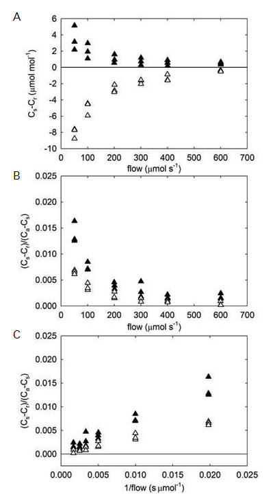
When photosynthetic rates are not corrected for diffusional fluxes, there can be significant over- or under-estimation of the actual rates (see Flexas et. al., 2007, Rodeghiero et. al., 2007), though the effects are dependent on the magnitude and direction of the concentration gradient. When the chamber CO2 and H2O concentrations are at the same concentration as the surrounding bulk air, there is no gradient and thus no diffusion. As the concentrations within the sample chamber are driven away from ambient, diffusion gradients cause CO2 and HO2O to move between the chamber and the surrounding atmosphere. These fluxes create erroneous differences between the reference and sample infrared gas analyzers (IRGAs; Figure 1‑1, A). When the chamber concentration is less than ambient, the net flux is into the chamber, leading to an underestimation of the photosynthetic rate, because the difference between the sample and reference analyzer concentrations is decreased. Conversely, when the sample chamber gas concentrations are above ambient, the net flux is out of the chamber, resulting in a larger difference between analyzers and an overestimation of the net photosynthetic rate.
Since the LI-6400/LI-6400XT is an open system, the magnitude of the difference between infrared gas analyzers (IRGAs) is dependent on the flushing rate through the system; faster flow through the system minimizes the apparent effect (but not the resulting error in flux). In the example data, the leak-caused difference in an empty chamber is < 2 µmol mol-1 CO2 at flow rates greater than 400 µmol s-1 (the recommended minimum flow for these chambers). See the Using the LI-6400/LI-6400XT manual, Chapter 4 for further discussion and example effects (LI-COR, 2009). Leaks normalized to the CO2 gradient for the new Opaque Conifer Chamber were proportionally very small (< 0.003) at flow rates > 400 µmol s-1 (Figure 1‑1, B).
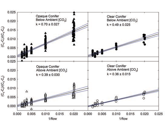
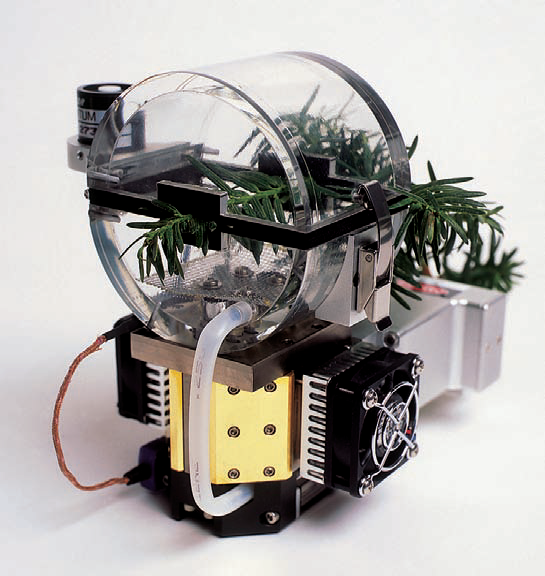
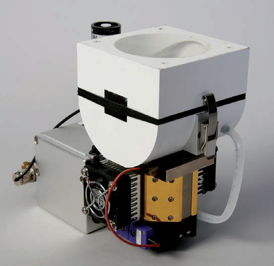
In testing of the 6400-22 Opaque Conifer Chamber (OCC) and 6400-05 Clear Conifer Chamber (CCC), the large gasket perimeter resulted in a small inherent leak. Following the described methods (LI-COR, 2009), the leak rate (k) was found to be dependent on the direction of the CO2 concentration gradient. Chamber CO2 concentration below ambient air concentration resulted in a greater inward leak (greater k) than when chamber CO2 concentration was above ambient (Figure 1‑2).
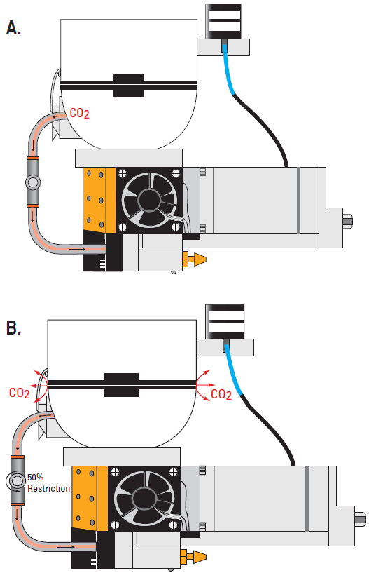
Exhaust Flow Restrictions: The LI-6400XT is an open, flow-through system in which environmentally-conditioned air enters the chamber, forcing an equal volume out the exhaust path. When the OCC or CCC is used to measure low photosynthesis or respiration rates, the user can employ a flow-restricting needle valve (part number 9864-310) to restrict flow out of the chamber exhaust port (Figure 1‑3). By restricting the exhaust flow, pressure inside the chamber is increased slightly (0.10 to 0.18 kPa) as air is forced through the gaskets. This flow through the gaskets creates a stable and measurable leak rate in the OCC and CCC. Typically, closing the needle valve to 25 to 50% is sufficient to divert enough flow through the gaskets, while maintaining sufficient flow through the match valve to match the IRGAs.
While there is an apparent increase in the CO2 and H2O concentrations caused by the increased pressure in the sample analyzer, matching the IRGAs will remove this offset. This is possible because the reference analyzer is downstream from the restriction and remains at ambient pressure (unpressurized). The sample analyzer is adjusted to match the reference resulting in pressure-corrected concentration measurements and flux calculations.
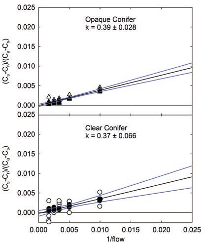
The leak rates for both the OCC and CCC were measured with the exhaust air flow restriction. With just 25% closure of the needle valve, the leak rate was the same when CO2 concentration inside the chamber was below or above ambient (Figure 1‑4). When working at low fluxes (low photosynthesis or dark respiration), the impact of leak related errors is greater than at high fluxes. Fortunately, the exhaust restrictions created a constant leak rate in these chambers. With a constant leak effect, the user can correct the CO2 flux rates based on the measured leak rate from the chamber. A method for calculating the leak rate coefficient (k) is described in the Using the LI-6400/LI-6400XT manual, Chapter 4 (LI-COR, 2009). Once k has been measured experimentally, the user can refine the water-corrected photosynthetic rate, as reported by the LI-6400/LI-64000XT. The fully corrected photosynthetic rate (A) would be:
1‑1

where F is the flow rate, Cr is the reference CO2 concentration, Cs is the sample CO2 concentration, Ca is the CO2 concentration outside the chamber (ambient), E is the transpiration rate, and S is the leaf area in cm.
Conclusion
Diffusion along CO2 gradients created by leaf chambers is problematic at low photosynthetic and respiration rates. The uptake errors that result from diffusion can be corrected by experimental methods. Establishing a constant leak rate in the OCC and CCC is facilitated by restriction of the exhaust path, which forces air out alternative pathways thereby stabilizing the leak rate. Once a stable leak rate has been established, the user can measure it experimentally and apply the appropriate correction.
Bibliography
| 1 | Flexas J, Diaz-Espejo A, Berry JA, Cifre J, Galmes J, Kaidenhoff R, Medrano, H, Ribas-Carbo M (2007) Analysis of leakage in IRGA’s leaf chambers of open gas exchange systems: Quantification and its effects in photosynthesis parameterization. Journal of Experimental Botany, 58, 1533-1543. |
| 2 | Jahnke S, Pieruschka R (2006) Air pressure in clamp-on leaf chambers: A neglected issue in gas exchange measurements. Journal of Experimental Botany, 57, 2553-2561. |
| 3 | LI-COR (1998) Using the LI-6400 Portable Photosynthesis System, Lincoln, NE, LI-COR Inc. |
| 4 | LI-COR (2009) Using the LI-6400/LI-6400XT Portable Photosynthesis System, Lincoln, NE, LI-COR, Inc. |
| 5 | Long SP, Bernacchi CJ (2003) Gas exchange measurements, what can they tell us about the underlying limitations ot photosynthesis? Procedures and sources of error. Journal of Experimental Botany, 54, 2393-2401. |
| 6 | Long SP, Hällgren JE (eds) (1993) Measurement of CO2 assimilation by plants in the field and laboratory, London, Chapman and Hall. |
| 7 | McDermitt DK, Garcia RL, Wells JM, Demetriades-Shah T (2000) Common Errors in Gas Exchange Measurements. In: Probing Photosynthesis Mechanisms, Regulation and Adaptation. (eds Yunus M, Pathre U, Mohanty P) . London, Taylor & Francis. |
| 8 | Pieruschka R, Schurr U, Jensen M, Wolff WF, Jahnke S (2006) Lateral diffusion of CO2 from shaded to illuminated leaf parts affects photosynthesis inside homobaric leaves. New Phytologist, 169, 779-787. |
| 9 | Rodeghiero M, Niinemets U, Cescatti A (2007) Major diffusion leaks of clamp-on leaf cuvettes still unaccounted: How erroneous are the estimates of Farquhar et al. model parameters? Plant Cell and Environment, 30, 1006-1022. |