
Printable PDF: Installing the Peltier Cooler Kit
Instructions for thethe 6400-91 Peltier Cooler Kit
There are two Peltier thermoelectric block coolers located on either side of the LI-6400/XT sensor head, beneath the two fans and heat sinks. The block coolers regulate the temperature of the air that is circulated through the leaf chamber. The coolers can fail in one of two ways; they can fail completely, whereby there is no change in the block temperature, or they can become inefficient, and fail to modify the block temperature over their specified range. In the case of total failure, one or both of the coolers are physically broken, and exhibit an open circuit condition. If the coolers function, but will not change the temperature sufficiently, the resistance of the cooler(s) is likely too high, rendering it inefficient. This document describes how to test the Peltier coolers (this requires an ohmmeter), and replace, if necessary. The 6400- 91 Peltier Cooler Installation Kit includes one Peltier cooler, and additional parts required for the repair, including:
| Quantity | Description | Part Number |
|---|---|---|
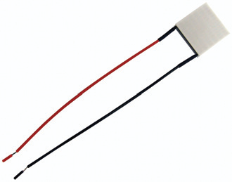
| 1 | Peltier Cooler | 435-04171 |
| 2 | Black thermal conductor pads | 108-03376 |
| 2 | Shrink wrap | 220-00291 |
Tools required:
- Ohmmeter
- 5/64” hex key (allen wrench)
- Wire cutter/stripper
- Soldering iron and solder
- Philips head screwdriver
- Tweezers
- Heat gun or butane lighter
Troubleshooting
- See if the fans spin freely
- The LI-6400XT has circuitry that senses if the fans for the coolers are running. If the fans do not turn, power will not be applied to the coolers. Blow on the fan blades and see if they turn. If they do not spin freely, they may be jammed; dislodge the impediment, and the problem may be solved.
- Check the fuses
- There are two fuses inside the LI-6400XT console, along the edge of the lowermost circuit board, labeled TEC- and TEC+ (Figure 1). Check these two fuses before proceeding. Center the fuse(s) in the clip holder to make sure it has good contact; if the sides of the clip holder are flared outward, remove the fuse and pinch the clip until it makes tight contact with the fuse.
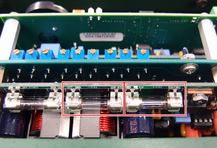
- Figure 1‑1. Check the fuses at TEC- and TEC+, highlighted above.
- Test the resistance of the cooler(s)
-
- Turn the LI-6400XT off and let it sit, untouched, for at least one hour so that both sides of the Peltier coolers are at the same temperature.
- Remove the three screws that secure the bottom cover of the sensor head IRGA (Figure 1‑2). You may have to pry the back end of the cover, and lift it enough to clear the log button and light sensor connectors on the side.
- Figure 1‑2. remove the three screws that secure the bottom cover.
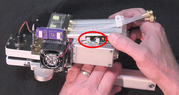
- Figure 1‑3. Pry the bottom cover off, taking care not to damage the log switch and light sensor connectors (highlighted).
- Follow the red and black wires from the coolers, and locate the two 4-pin white connectors on the edge of the circuit board (Figure 1‑4). The red and blue wires are the fan wires, and the other two are the cooler wires. Note that newer LI-6400XTs have red and black fan wires, so be sure to follow the correct wires back to the connector if your fan wires are red and black.
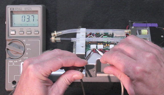
- Figure 1‑4. Follow the wires from the fan to the connector, and take a resistance reading at the connector. Polarity does not matter.
- You will need to take a resistance reading for the two cooler wires at the white connector. Since an ohmmeter sends a small current through the device under test, it will cause a good cooler’s resistance reading to change as soon as you touch the leads to the pins on the connectors. Make sure you have the ohmmeter in a position to read the display, touch the leads to the cooler wires (polarity does not matter), and immediately observe the reading (Figure 4). A cooler that is ‘good’ will read under 5 ohms. If the reading is between 5 and 15 ohms, the cooler will operate, but at a lower efficiency. If the reading is over 20 ohms, open (infinity), or in the k ohms range, the cooler has failed and should be replaced.
Installing the Replacement Coolers
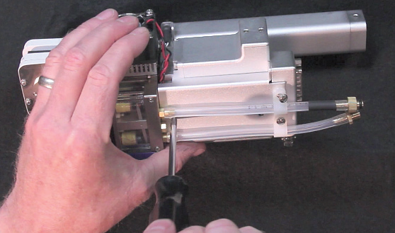
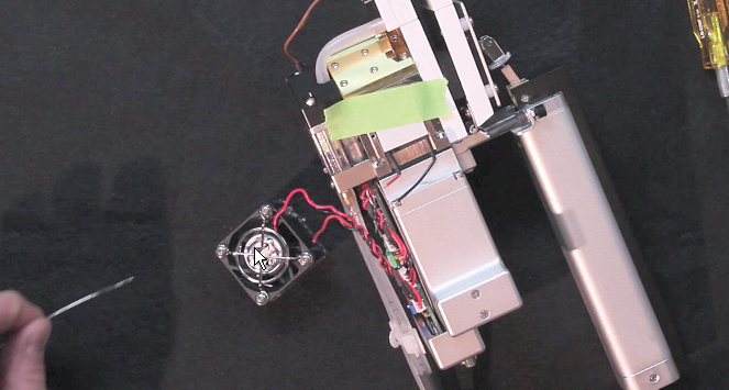
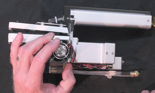
- Don’t remove the four screws in the corners of the fan assembly; it’s much easier to remove the entire fan/heat sink assembly by inserting the 5/64” hex key down through the fan housing and loosening the two hex head screws (Figure 1‑5). Try not to let the screws fall completely out of the fan assembly; it’ll be easier to re-install later if they’re still inserted into the holes in the fan assembly. This will remove the fan/heat sink assembly, and expose the block cooler.
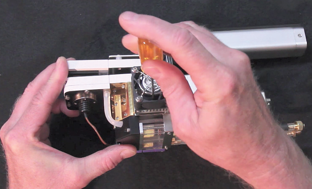
- Figure 1‑5. Insert the hex key through the fan housing and remove the two hex screws that hold the fan/heat sink assembly.
- Note that there is a thermal conductor pad on the underside of the heat sink (Figure 1‑6). Replacement pads can be found in the kit; the pads do not need to be replaced unless they are damaged.
- Note that the red wire is located on the top of the cooler on the right side of the sensor head, and on the bottom of the cooler on the left side of the sensor head (Figure 1‑6). This is important, as the coolers are in series with each other, and work together; if one of the coolers in installed backwards, the coolers will work against each other.
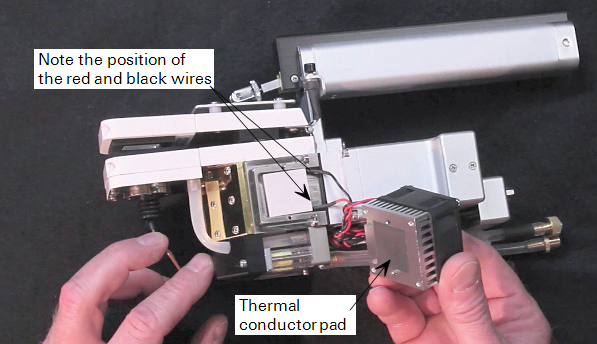
- Figure 1‑6. Note the thermal conductor pad on the bottom of the heat sink. Note, too, that the red wire is on the bottom of the cooler on the left side of the sensor head.
- Use a pair of tweezers or a small screwdriver to pry around the edges of the cooler; it may be stuck to a second thermal conductor pad underneath, and may need to be pried off. Loosen the cooler, but leave it in position for now.
- Use a pair of wire clippers and clip both of the cooler wires about 1/2” past the black heat shrink, just past where the wires make a 90 degree bend, as shown in Figure 1‑7.
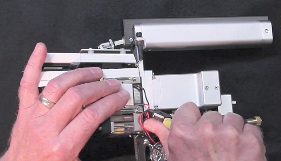
- Figure 1‑7. Clip both wires about 1/2” below the heat shrink.
- Lay the new replacement cooler over top of the old one, and bend the wires on the new cooler to match those of the old cooler. Again, make sure the black and red wires are oriented correctly. Clip the wires on the new cooler to a length slightly longer than those that were clipped on the old cooler. Remove the old cooler and discard.
- Strip about 1/16” of the insulation off the two cooler wires. Unwrap the wires from the fan/heat sink assembly for a short distance, and strip the insulation from them as well, about 1/16”. Tin all four exposed wire ends with your soldering iron.
- Place the new cooler in position on the sensor head, on top of the thermal conductor pad (replace the pad if it was damaged while removing the old cooler). Before soldering the wires together, it may be useful to place a piece of masking tape over the cooler to hold it in place while you solder the wires (Figure 1‑8).
- Figure 1‑8. Place a piece of tape over the cooler to hold it in place while soldering the wires, if necessary.
- Place a piece of heat shrink over one of the black and red wires; they’ll be used later to seal the soldered joints.
- Use a pair of tweezers to hold one wire steady against the other as you solder the ends (Figure 1‑9). Place the exposed ends side by side to create a lap joint. Use a freshly tinned soldering iron and solder the ends together. Use the tweezers to slide the heat shrink over the newly soldered joint (Figure 1‑10). Repeat for the other wire joint. Use a heat gun or a butane lighter to seal the shrink wrap; pass the flame over the heat shrink until it contracts over the joint.
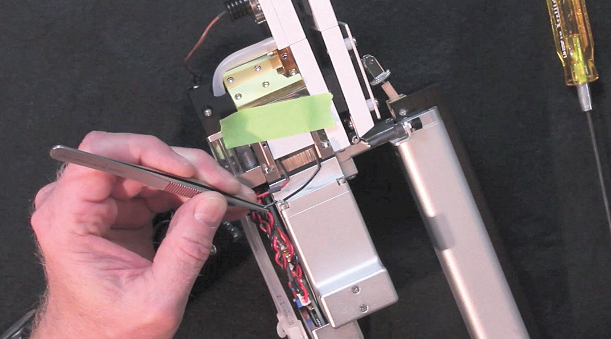
- Figure 1‑9. Use a pair of tweezers to hold the ends together while you solder the exposed wire ends.
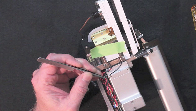
- Figure 1‑10. Slide the heat shrink over the soldered joints.
- Note that there are two milled grooves on one side of the heat sink, as shown in Figure 1‑11. These grooves face the back of the sensor head, at the 3 o’clock position. The wires from the cooler must lay in these grooves when installing the fan/heat sink assembly, so that the wires don’t get pinched.
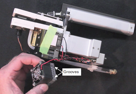
- Figure 1‑11. Note the two grooves in one side of the heat sink; these grooves face toward the back of the sensor head, at the 3 o’clock position.
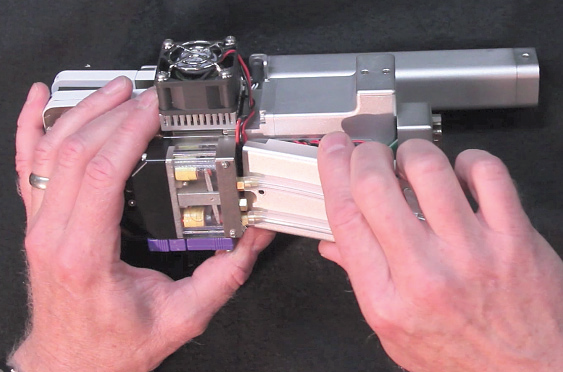
- When the cooler wires are routed through the heat sink grooves, put the fan/heat sink assembly into position and start, but don’t tighten, the two hex head screws. Alternate tightening between the two screws. Tighten only until you feel the screws stop; do not overtighten, as the ceramic cooler underneath can be damaged.
- Reassemble the lower cover. Make sure the cooler and fan wires on both sides are not pinched between the cover and the IRGA block; use the tweezers, if necessary, to position the wires in the two grooves on the front edge of the lower cover (Figure 1‑12). Make sure that none of the other wires are pinched, and snap the lower cover into place. You can slide the lower cover back and forth at the leading edge, nearest the coolers, to see if the wires are pinched; you should feel metal on metal when the cover is positioned properly (Figure 1‑13).
- Figure 1‑12. Make sure the wires aren’t pinched underneath the heat sink before tightening the screws on the fan/heat sink assembly.
- Figure 1‑13. Position the wires in the grooves at the front edge of the bottom cover. Snap the cover into place, rock the cover at the leading edge to make sure the wires aren’t pinched, and reattach with the three screws.