
Attaching the Soil Chamber
General Description
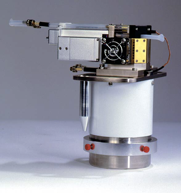
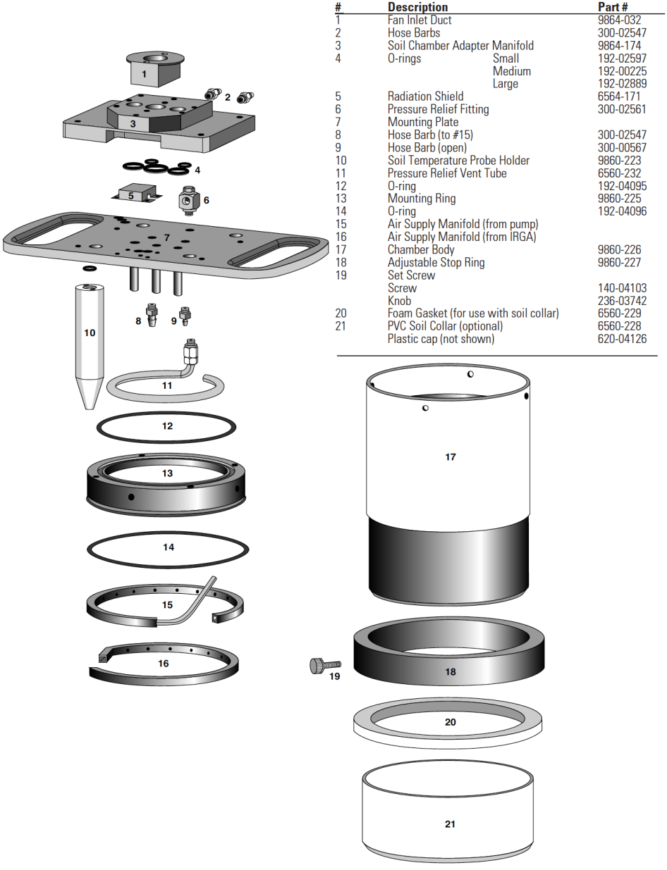
Figure 28‑4 shows the 6400-09 Soil Chamber attached to the LI-6400 sensor head, and Figure 28‑5 is an exploded diagram showing the parts of the Soil Chamber, along with a detailed parts list should you need to order individual pieces.
Attaching the Soil Chamber to the Sensor Head
The following steps take you through the removal of the standard leaf chamber from the sensor head, and the attaching of the soil chamber.
- Remove the standard leaf chamber
- Refer to Figure 28‑6.
-
- Remove the male end of the leaf temperature thermocouple connector by pulling straight out.
- Unplug the log switch connector.
- Unplug the light sensor connector.
- Unplug the LED power connector (if LED source is attached).
- Pull the air hose from the underside of the leaf chamber.
- The log switch
- The log switch is not used with the soil chamber. If the log switch wires are threaded underneath the bottom cover of the sensor head, this cover must be removed to free the log switch (Step 3). (When it is time to put the standard chamber back on, you can save yourself some work and not re-thread the log switch wires beneath this cover.)
- If the log switch wires are not threaded beneath the cover, skip to Step 4
- Remove the bottom cover (if necessary to free the log switch)
-
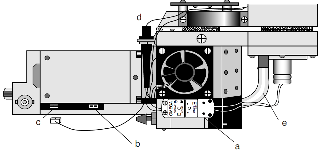
- Turn the sensor head over and remove the 3 Phillips head screws as shown in Figure 28‑7.
- Remove the hose barbs, if necessary. You may be able to slide the cover out from underneath the hose barbs; be careful not to damage the PC board under the cover. If you remove the hose barbs, note the position of the sample and reference air hoses; the sample hose is wrapped with a piece of black shrink wrap.
- Free the wires.
- Re-assemble the sensor head bottom cover. Be very careful not to pinch any wires when replacing the cover.
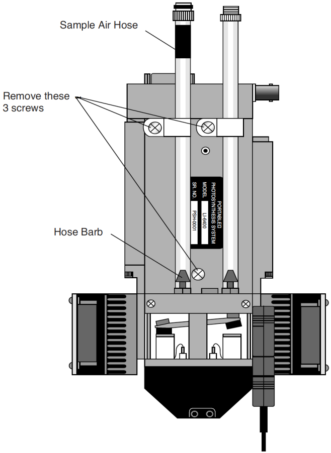
Figure 28‑7\. Preparing to remove the bottom plate. - Remove the handle assembly:
- Unlatch the handle, and unscrew the knurled leaf chamber adjustment nut (turn clockwise) until it is free of the handle (Figure 28‑8).
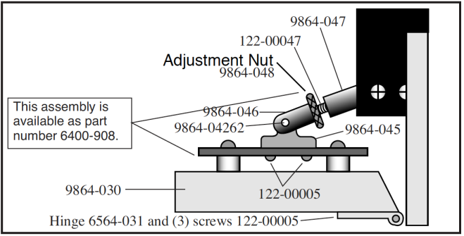
Figure 28‑8. Turn the adjustment nut clockwise to remove. - With the handle latching mechanism in the closed position, wrap tape or string around the handle (where your hand would normally be) so that it will stay together. Failure to do so may result in the rear spring coming out. Leave the handle secured in this manner.
- Remove the two screws (three on some instruments) on the back side of the handle, as shown in Figure 28‑9, using a #1 Phillips head screwdriver. Be careful not to lose the spacer that is between the handle mounting plate and the hinge.
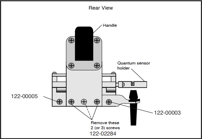
Figure 28‑9. Remove the screws on the back side of the handle.
- Remove the upper half of the chamber
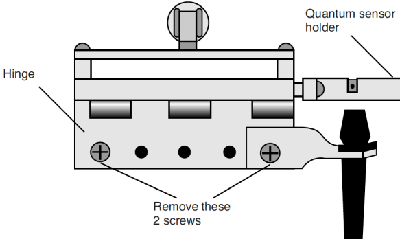
- Remove the 2 screws from the hinge on the rear of the upper half of the leaf chamber (Figure 28‑10).
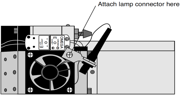
- Remove one fan shroud screw and attach the lamp connector (Figure 28‑13).
- Remove the lower half of the chamber
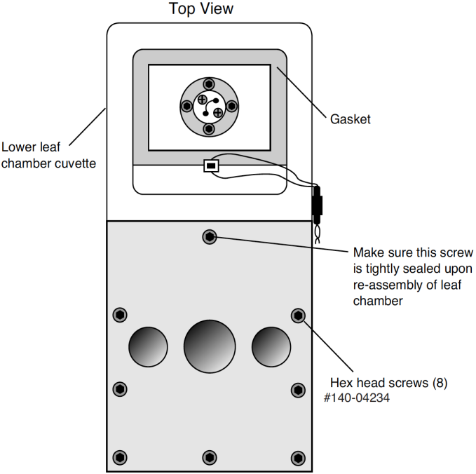
- There are eight hex head cap screws on the optical bench cover, as shown in Figure 28‑12. Remove the cap screws with a 5/64” hex key (in the spares kit). The lower half of the leaf chamber can now be removed.
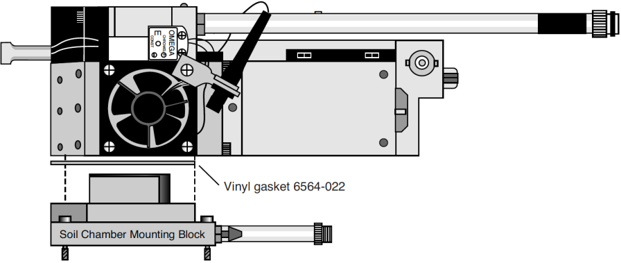
- Attach the soil chamber mounting block
- Use the 8 hex head cap screws from the previous step. The proper orientation of the mounting block is shown in Figure 28‑13. Note the thin vinyl gasket on the top surface of the optical bench. This gasket is reusable; it should adhere to the optical bench, but if it becomes detached, be sure to reposition it before attaching the mounting block. Tighten the 8 screws carefully and evenly. Note that the screw nearest the leaf chamber forms a metal-to-metal seal in the air pathway, and must be tight upon re-assembly of the standard leaf chamber.
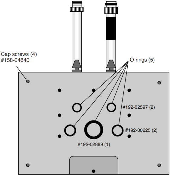
- Check the O-rings
- Make sure all O-rings are properly positioned, as shown in Figure 28‑14.
- Attach the chamber body to the mounting block
- Attach the 6400-09 body to the sensor head/mounting block assembly using the 4 cap screws (use the 5/64" hex key included), located on each corner of the mounting block (Figure 28‑15).
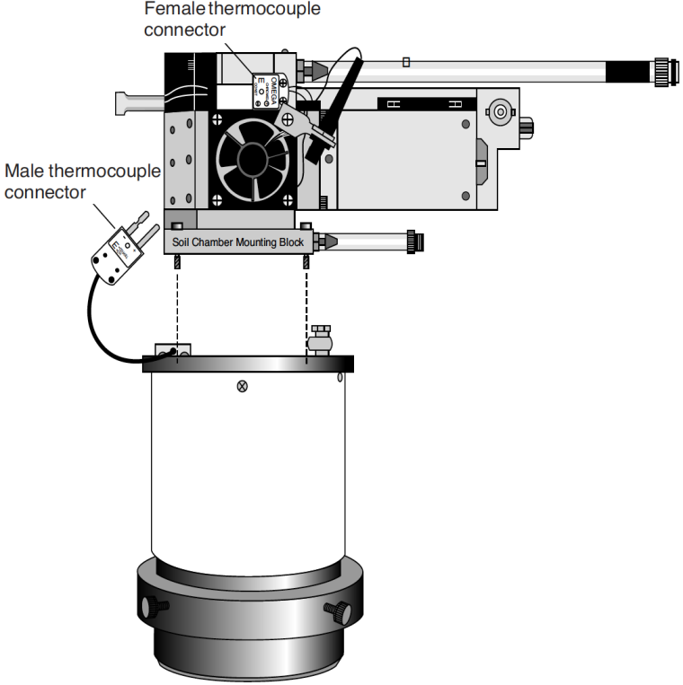
- Connect the air temperature thermocouple
- There is a thermocouple in the soil chamber that measures air temperature. Its connector plugs into the connector normally used for leaf temperature on the sensor head.
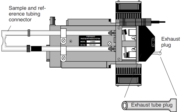
- Join the sample and reference tubes
- Connect the tubes together on the sensor head with the “U” shaped piece of tubing, in the 6400-09 replacement parts kit (Figure 28‑16). Also, insert the exhaust tube plug onto the match valve’s chamber port. The main purpose of these items is to keep dirt out of the (now unused) match valve and air lines going to the IRGAs.
- Connect the air supply hoses
- The two long air hoses in the LI-6400 cable bundle connect as follows: On the chamber end, connect to the tubes coming from the chamber connection block (shown in Figure 28‑14) instead of to their normal place on the sensor head (i.e. the tubes shown in Figure 28‑16). The tubes with the black shrink wrap connect to each other.
- On the console end, connect as shown in Figure 28‑17. The tubing with black shrink wrap connects to a “Y” connector (in the spares kit), and on to the sample and reference ports. The second hose leading from the soil chamber is connected to the Air Inlet port on the console with a short adapter tube (also in the spares kit).
- A schematic of the proper overall plumbing is shown in Figure 28‑2.
- Connect the soil temperature probe to the LI-6400 console
- The 6400-13 thermocouple adapter assembly is in the spares kit. The adapter plugs into the 37 pin auxiliary port on the LI-6400, and the soil temperature thermocouple plugs into the adapter.
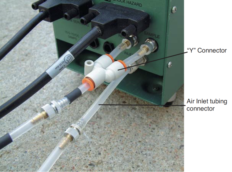
NOTE: Make sure the two short pieces of tubing are FULLY seated into the two legs of the Y connector. If one of them is not, it will leak, creating problems when pulling the chamber CO2 concentration below ambient during the drawdown phase of the measurement.
Assembly is now complete.