CO2 Tank Connector Block
Printable PDF: CO2 Tank Connector Block
Installation instructions for the 9964-033 CO2 Tank Connector Block, for situations where a CO2 source of longer duration than can be provided by the CO2 mini-cartridges is needed.
The tank connector block is designed for use at pressures between 180 and 220 PSIG of CO2. Do not exceed 250 PSIG CO2, as the pressure relief valve may vent.
The tank mounting block is fitted with a 1/8” male NPT to 1/8” tubing fitting. This fitting is installed with a 10 SCCM flow restrictor. Do not remove this fitting. A 1/8” to 4 mm compression union is also provided for users who may be unable to obtain 1/8” copper tubing. Directions for installing the tank connector block to a CO2 source using 4 mm copper tubing are given on the reverse.
Installation
- Remove the red protective plastic cap covering the CO2 inlet on the LI-6400 case, between the CO2 and H2O scrub tubes.
- The CO2 tank connector block is mounted on the left side of the LI-6400 console, between the CO2 and H2O scrub tubes. Make sure that the O-ring seal on the back of the block is properly seated. Tighten the two knurled knobs on the mounting block to secure the assembly to the console.
- Insert a length of 1/8” copper tubing through the 1/8” connector nut and the ferrule.
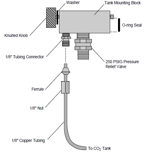
Important: Note the orientation of the ferrule. One of the tapered ends of the ferrules is longer than the other; the long end must be oriented toward the connector on the mounting block. When the nut is tightened onto the connector, the ferrule will be permanently crimped to the copper tubing, and you will not be able to remove it.
- Tighten the nut until snug, plus 3/4 of a turn.
- Connect the other end of the copper tubing to your CO2 source. Adjust the tank pressure to between 180 and 220 PSIG.
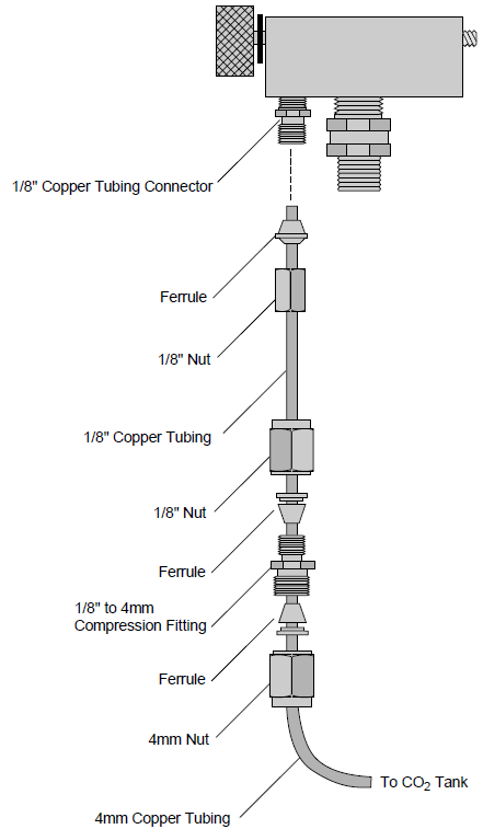
Installation Using 4 mm Copper Tubing
If you are unable to obtain 1/8” copper tubing, it is possible to connect the tank connector block to a CO2 source using 4 mm tubing and the compression fitting (LI-COR part #300-04439) included with the tank connector block.
- Install the tank connector block and the short length of 1/8” copper tubing (included) as described in steps 1-4 above.
- Use the 1/8” to 4 mm compression fitting to connect the 1/8” and 4 mm tubing, as shown in Figure 2. Be sure to orient the ferrules correctly; the narrow tapered end of each ferrule must be oriented toward the compression fitting. Tighten the nuts on the compression fitting until snug, plus 1 1/4 turn.
- Connect the 4 mm tubing to your CO2 source. Adjust the regulator pressure to between 180 and 220 PSIG.