
6400-18 RGB Source
Communication Problems
When it needs to synchronize with the 6400-RGB Source, the console checks to see if the connector is attached. If it is not, you will see the message shown in Figure 20‑12.
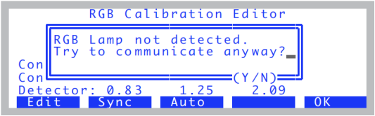
Once the connector is plugged in and the RGB Source powered, the problem (and the message) should go away.
Fan Issues
The RGB source fan operates when it needs to. Here is its logic:
- Fan on: IF (T > 52 AND V>14.0) OR (ON AND (T > 30)).
- Fan off: IF (V < 14.0) OR OFF OR (T < 26)
where ON and OFF refer to the LEDs, T is the heat sink temperature (C), and V is the voltage supply (V). In other words, the fan will run if the heat sink temperature exceeds 52C and the supply voltage is > 14V, or if the LEDs are on and the heat sink temperature gets above 30C. The fan will turn off if the battery is <14V, or if the LEDs are switched off, or if the heat sink temperature drops below 26C.
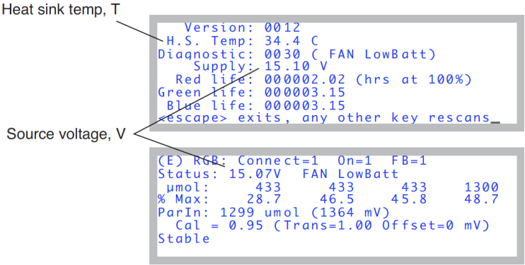
Temperature T and voltage V can be viewed using the Query function key (f2 level 3) of Home Menu|RGB Control Panel (see RGB Control Panel on page 21-9 in the instruction manual). V can also be viewed in the Light Status window of New Measurements mode (press [ then e).
Warning Message
If the 6400-18 Light Source is being used, any combination of warning or error conditions can generate a New Measurements mode warning message:
>> RGB Source: FAN / WARM / HOT / 5V / LowBatt / DeadBatt <<
The following words mean the following things:
- FAN - The fan is on. (This by itself won’t trigger a warning message, but will appear in the list of status items if it is on).
- WARM - This is a warning that it is too warm. Specifically the heat sink is warmer than about 70C.
- HOT - The heat sink is warmer than 80C, so the LEDs will not be allowed to turn on.
- 5V - The 5V supply is not in the range of 4.5 to 5.5 V.
- LowBatt - The voltage supply is < 15.7 V. This message will only appear if the RGB Source senses that it is connected to a battery. This determination is made when power is first applied. If the detected voltage is 17.25V, it is assumed to be a battery.
- DeadBatt - Dead battery indicator. V<14.0V.
Note: The RGB items listed in the New Measurements warning message are also viewable in the two RGB Status screens (Figure 20‑13).
LEDs Switched Off
Check a status display (Figure 20‑13) for the voltage level, or for the DeadBatt label. When the supply voltage drops below 14V, the LEDs will switch off. To get them to turn on again, you must first replace the discharged battery, then turn on the light source using the normal method in New Measurements mode (f5 level 2). If you aren’t using a battery, then verify that all the necessary cables are plugged in.
Doesn’t Reach Target
Out of reach?
When operating in Q or T modes (Quantum or Tracking), the light source is color-constrained. That is, it will give highest priority to keeping the color constant, even if it means it can’t reach your target. Typically, the maximum red only output is 1300 μmol m-2 s-1 or more, green is 900, and blue is 1200. So if you are trying to get 2500 μmol m-2 s-1 with cyan (green + blue, no read), you may not get there.
Transm OK?
There is a multiplier that stands between what the lamp is doing and what the ParIn_μm value says. See The Transm Factor on page 8-20 in the instruction manual. Verify that is what you expect it to be for the geometry you are using. A quick way to check it is to look at the Lamp Diagnostics screen in New Measurements mode (press [ then E).
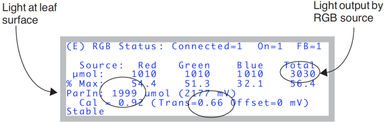
In Figure 20‑14, we see the ParIn value is 2000 μmol m-2 s-1, which is our target. But notice that transm is 0.66, so the lamp is having to put out 3030 μmol m-2 s-1 to meet that. (That’s a lot, and you may not always get that, especially on a hot day). Transm lives in the configuration tree at <open> <light> <source> <par_in> <sensor> <cal> <transm>, and you can adjust it there (Figure 20‑15).
Gets there slowly?
Start with the lamp off. Then specify a Q target. The parIn_μn value should get to within 1% in the averaging time of the analog measurements (default is 4 seconds). A few seconds after that, it should lock in exactly. If the first guess poor, try re-doing the user calibration (RGB Calibration Editor).
Something is Goofy
This is obviously a catch-all, but a good place to spot the root of a myriad of possible problems is in the Calibration Editor (Figure 20‑16).
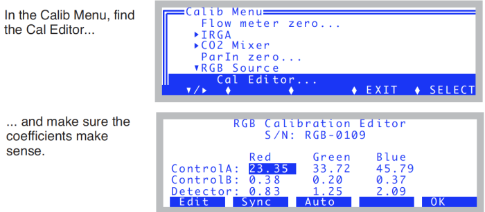
Compare these to the ones on your cal sheet. The top six will change when you run a calibration (f3, Auto). The bottom three are the factory calibration values, and they should be as printed. The Sync button (f2) forces a re-read from the RGB Source.
If you need to re-enter some factory values, position the highlighted box with the arrow keys, and press Edit (f1). If something bad has happened and you need to re-enter everything, including the serial number, here’s a hint (and a reward for reading the manual): press ctrl + s to edit the serial number.