
Printable PDF: Adding Wireless Connectivity to the LI-6400XT In Five Easy Steps
Instructions for adding the AirPort wireless router to the LI-6400/XT.
Wireless connectivity for the LI-6400XT has been a frequently requested option, mostly to enhance the ease of remote control of the instrument or to provide an easier way to download data. Although not a native feature, it is possible to modify the LI-6400XT to either join or create a wireless network through the addition of a modified Apple AirPort Express™. This document will detail the steps needed to add wireless capability to the LI-6400XT. Note that this modification works only for XT instruments since it relies on connecting the LI-6400XT via Ethernet to the AirPort Express.
Required Equipment
- Apple Airport Express Base Station (MC414LL/A)
- DC-DC adjustable step-down voltage regulator (we used Arrela Lm2596)
- Red and black 22 AWG wiring
- Controlled DC power supply
- DC voltage meter
Required Tools
- 3/4" putty knife and/or flat-head screwdriver
- 3M Double-sided urethane foam tape
- Red and black 22 AWG wiring
- Torx T8 screwdriver
- Torx T5 screwdriver
- Solder and soldering iron
- Nail polish or threadlock
- Wire stripping tool
Step 1: Disassembling the Apple AirPort Express™ Base Station
First and foremost, verify that the AirPort Express works before performing any of the subsequent steps below. Plug it in, power it up, and make sure you can connect to it and access the firmware using the software provided by Apple. This assures you that if you have a defective router, it is addressed before you (A) go through making the modifications, and (B) before you void Apple’s warranty.
The AirPort Express is not designed to be taken apart by end-users; nevertheless, with some patience and the judicious application of force, it is possible to open the outer case without destroying the router. To do this, start on the side of router that contains the small LED. Begin prying with a flathead screwdriver or putty knife to the right of this side’s center. When the side starts to open up, move to the next side, taking care to not pry directly on the center connector resides. Continue prying each side, off-of-center, until the top of the AirPort Express is off. Note that the internal corner connectors will likely break off while removing the top cover; this is okay as long as the internal center connectors are not broken. Needless to say, you have voided the warranty provided by Apple at this point.
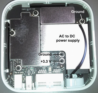
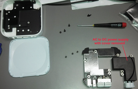
Once the AirPort Express is open, you should see something similar to Figure 1‑1. The goal now is to remove the power supply and replace it with the voltage regulator. The power supply is under the “L” shaped metal cover that is highlighted in Figure 1‑1. There will be five screws that need to be removed to get this cover off. These screws require the Torx screwdrivers listed above. When the metal shield is off, continue removing other screws holding down the circuit board; the entire circuit board needs to be removed from the AirPort Express case before it is possible to take out the power supply. The removed assembly should appear as in Figure 1‑2.
Step 2: Wiring voltage regulator terminals
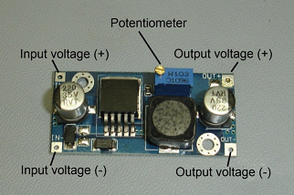
The voltage regulator is the component that makes is possible to run the AirPort Express off of a DC power source. The key components of the voltage regulator are shown in Figure 1‑3. The key steps are (1) solder wires to the input and output sides of this regulator and then (2) adjusting the output of the regulator to 3.3 V.
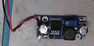
Cut approximately a 16-inch length of both the red and black wiring. These wires will be soldered to the “in” side of the voltage regulator. Strip approximately 1/4 inch of insulation off of each end. Using the soldering iron, put a small amount of solder on the ends of each wire. Then, form one end of each wire into a hook and hook these ends into the appropriate terminals in the voltage regulator (red wire to the positive terminal and black wire to the negative terminal; if using alternative colors, just keep your color convention consistent throughout). Solder the wires to the terminal by placing a small amount of solder on both the terminal and wire. To add some strain relief, you can twist the wires together a couple times as shown in Figure 1‑4.
The next step is to solder wires to the “out” side of the voltage regulator. Cut a 4-inch length of black and red wiring, again stripping 1/4 inch of insulation off of each of the four ends, soldering these ends, and then forming the ends into hooks. Solder one end of each wire to the appropriate terminal on the voltage regulator’s “out” side.
Step 3: Set voltage regulator
Setting the voltage regulator is the next step. However, a voltage of some kind needs to be applied to the incoming terminals. Then you can measure and adjust the voltage on the “out” side using a voltmeter. The supply voltage can be anywhere between about 4.3 - 30VDC. After a voltage is applied to the “in” side, monitor the voltage on the “out” side using a voltage meter and turn the potentiometer dial so that the “out” side voltage reads 3.3 V. See Figure 3 to better understand the voltage regulator and how to adjust it. Then, apply some nail polish or threadlock to the potentiometer dial to prevent inadvertently moving the dial later on. Then, check the voltage on the “out” side one more time. If the voltage on the “out” side isn’t adjusted to 3.3 V, the AirPort Express may not work correctly or could be damaged, thus releasing the device’s magic smoke.
Step 4: Connecting voltage regulator to the AirPort Express
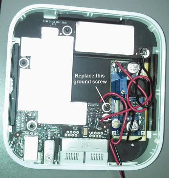
Connecting the voltage regulator to the AirPort Express simply involves soldering the two wires on the “out” side to the ground and +3.3 V terminals in the router. Solder the negative wire to the router’s ground terminal and solder the positive wire to the +3.3 V terminal (see Figure 1‑5). You can now tear off the remaining side of the double-sided sticky tape and place the voltage regulator into the AirPort Express on top of the sticky tape. Now, replace the ground screw as indicated in Figure 1‑6 using the appropriate Torx screwdriver. This will serve as a post for strain relief. The wires that are connected to the voltage regulator’s “in” side can be wound around this post before routing them through the AC cord connection hole in the AirPort Express case.

To test the new setup, apply DC power (4.3 - 30V) to the wires that lead out of the router. The router should appear as if it is booting up normally. If the router’s LED does not light up, or if you see sparks and smoke, something has gone awry.
Step 5: Connecting the AirPort Express to the LI-6400XT
There are a few options for powering the DC-powered AirPort Express. One option involves wiring to the internal LI-6400XT power supply. This is accomplished by soldering two wires to the LI-6400XT. In this case, the wires should be soldered to the switched +12V line and ground. Alternatively, one could design a ‘Y’ cable that plugs into an LI-6400 battery on one end, and then the other two ends would connect to the router and LI-6400 console. Finally, there’s always the option of just powering it using a separate battery.