
Using auxiliary channels
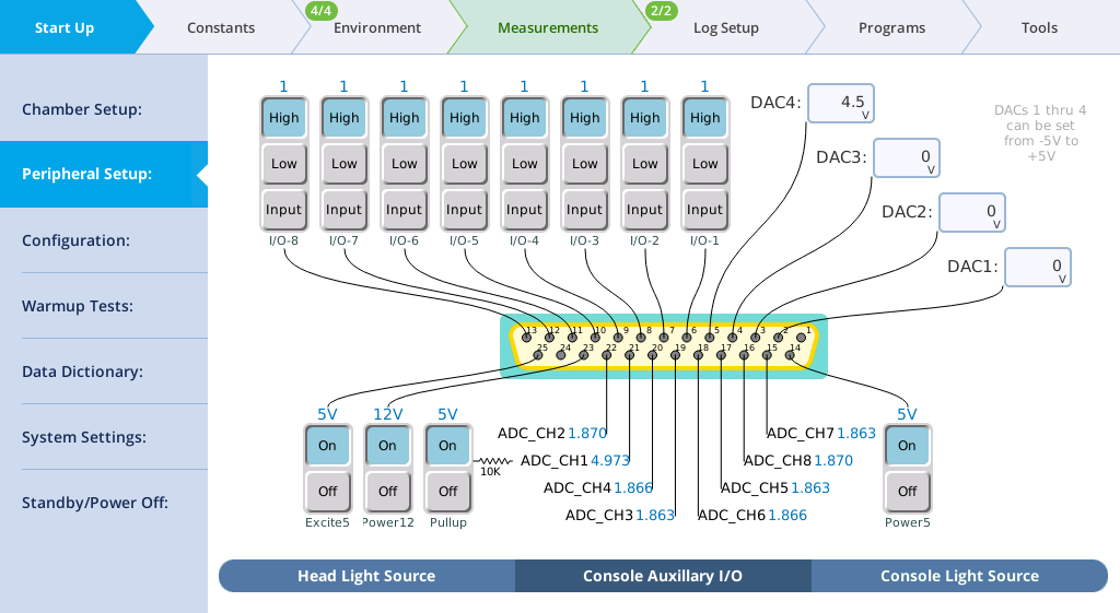
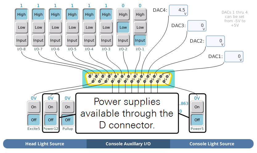
The LI-6800 can control peripheral components (such as mixing fans) and accept data from peripheral sensors (such as thermocouples) through the 25 pin D-sub connector (DB25). The connector is labeled USER I/O on the console; it is configured via the Start Up > Peripheral Setup > Console Auxiliary I/O. The outputs can also be controlled via the AutoEnv controls and from the generic Programs.
When using the aquatic chamber, some auxiliary channels are used by the chamber. See Using auxiliary channels with the aquatic chamber.
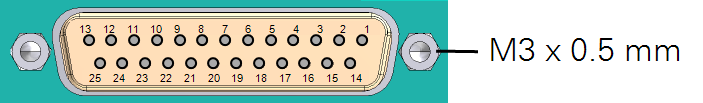
The LI-6800 25-pin connector accepts a male 25-pin D-connector, which can be purchased from many electronics stores or directly from LI-COR. Pin assignments are described in Table 9‑8. Raw voltages can be logged directly or transformed into more meaningful values using basic equations. This is described in User.
Logging the auxiliary channels
Logging of auxiliary channels is controlled under the Log Files > Logging Options tab. Under the Include in log file option, select Auxiliary. When you select auxiliary, all measured data and settings will be saved in the log file. Auxiliary data will be logged in the same row as the other data when you press the log button or when a log is initiated through a Program.
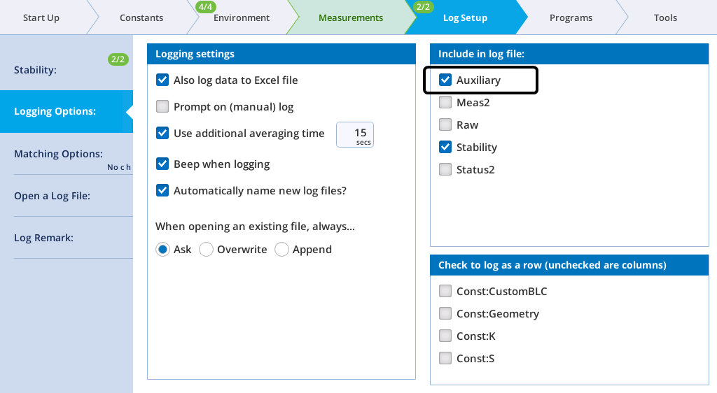
In addition to the inputs and outputs, the interface allows you to activate a 10 kiloohm 0.1% pullup resistor for 5 V biasing of a thermistor on ADC_CH1 (pin 21). The AuxPower feature is not supported yet.
Analog input channels
The eight ADC (analog-to-digital channel) inputs can read from ±5 volts at 16 bit resolution with a sampling rate of 10 Hz.
To wire an analog input, select a signal pin (pins 15 to 22) and a ground pin (pin 1 or 24). The sampling rate is fixed at 10 Hz, and thus the resolution is 152.6 µvolts per count.
Analog output channels
The analog output channels (DAC1 to DAC4) can be set to a fixed voltage in the Start Up > Peripheral Setup > Console Auxiliary I/O tab, or set to a shape (linear, step, sine/4, or sine/2) in Auto Controls and Programs. Output voltages range from -5 to +5 V. To set a fixed voltage, simply enter that value.
If you want to set a controlled parameter to track an auxiliary channel, see Auto Controls.
Digital outputs and inputs
Eight channels are available for use as digital inputs or outputs.
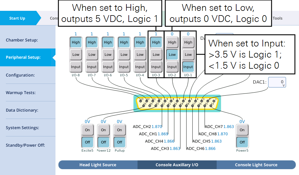
Tap High to output 5 V and Low to output 0 V through the corresponding pin. When used as a digital input, the voltage must be >3.5 V for logic 1 and <1.5 V for logic 0. The logic signals (pins 6 to 13) provide a very low current. Do not use them to power a device, since that could damage the circuitry.
Auxiliary power supplies
One 12 VDC and one 5 VDC power supplies are available through the connector.
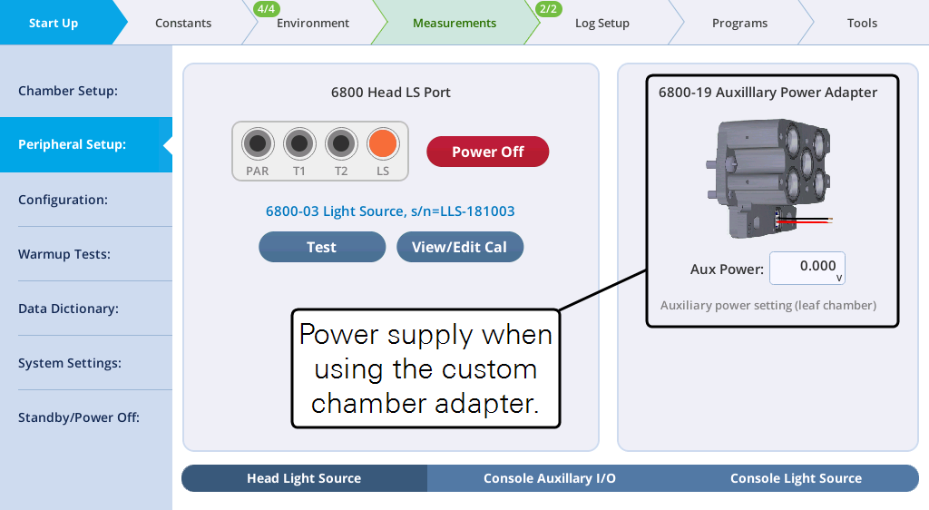
AuxPower is available when using the custom chamber adapter.
Mixing fan example
Here we'll describe how to connect an external mixing fan. The mixing fan may be used, for example, to ensure well-mixed air in a large custom chamber.
You'll want a small fan, like a fan used to cool a computer processor. It should be rated for operating at 12 VDC if you use pin 23 or 5 VDC if you use pin 14.
- Connect the red wire to pin 23 using a male DB25 connector.
- Connect the ground wire to pin 1.
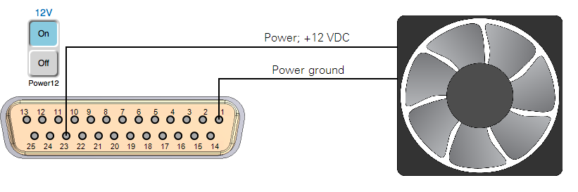
- Turn on the power.
- Under Start Up > Peripheral Setup > Console Auxiliary I/O, tap On for Power 12. The fan will turn on. Tap it again to turn the fan off.
Humidity and temperature sensor example
Here we show how to connect a Vaisala HMP155 humidity and temperature probe. Raw voltages can be logged directly or transformed into more meaningful values using basic equations.
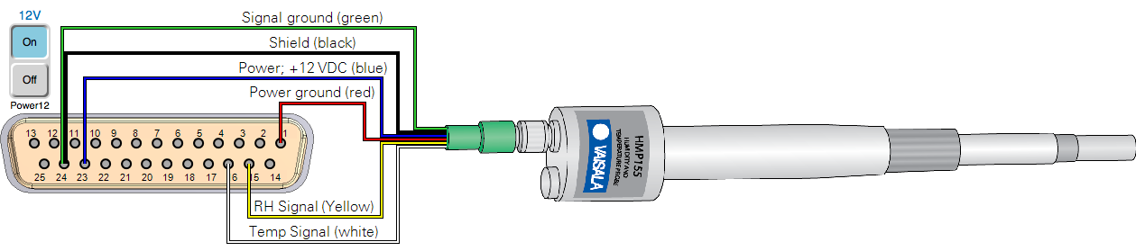
Be sure that the 12V power supply is on; and log the auxiliary channels in the data file (see Logging the auxiliary channels).
Configuring the auxiliary channels
The HMP155 outputs a voltage signal from 0 to 1 volt over a -80 to 60 °C temperature range and for 0 to 100% RH. You'll configure an equation with a slope and offset for temperature and an equation with a multiplier for RH. Start by creating a new User Constant for temperature.
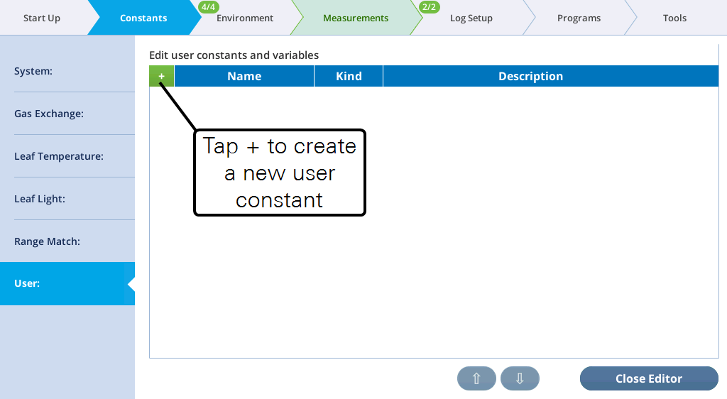
- Under Constants > User, tap the + button.
- Enter the Name, Units, and Description. Select Computed variable.
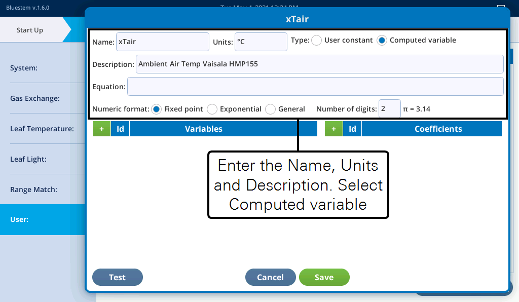
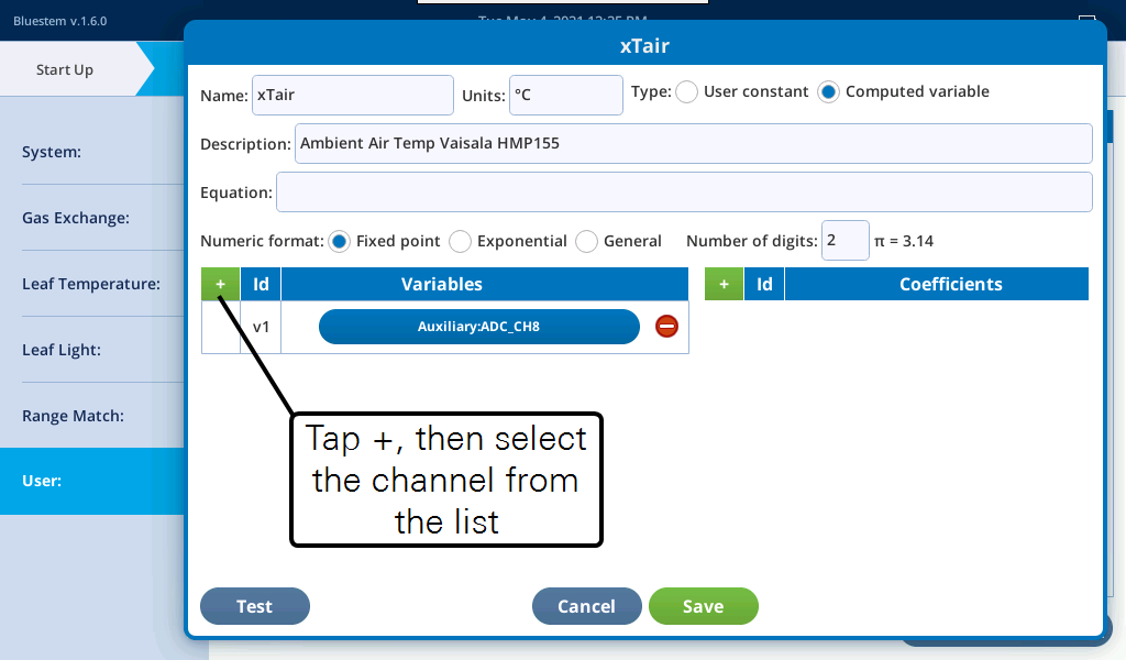
- Before entering the Equation, you should create the Variables and optionally, Coefficients.
- The equation for temperature in °C is
 , so enter the equation.
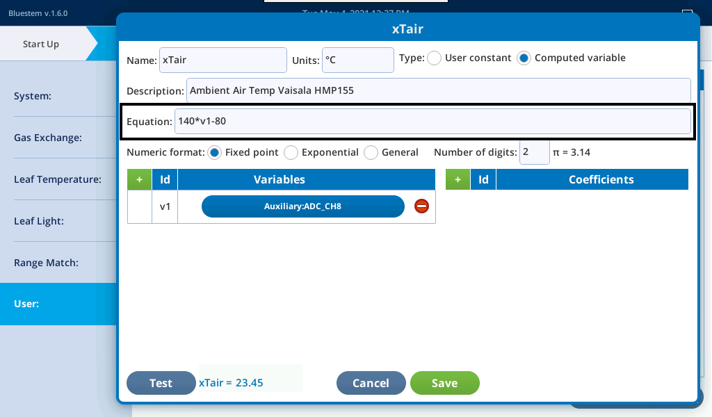
- Tap Test to see the results. If you're satisfied, tap Save.
- Create a new user constant for RH.
- Enter the parameters for the new constants
- The equation for RH% is
 .
. 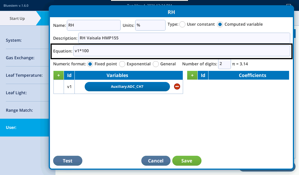
- Tap Save if you're satisfied with the configuration.
The auxiliary channels are available for use in programs and graphs. Be sure to log the auxiliary channels with your dataset (see Logging the auxiliary channels).