
Using the Small Plant Chamber
Printable PDF: Using the Small Plant Chamber
Download this content as a pdf that can be saved to your computer or printed.
Introduction
- The 6800-17 Small Plant Chamber is designed to measure whole plant photosynthesis for Arabidopsis thaliana as well as a variety of small plant types, including turf grass, that can be grown in 4 cm Cone-tainers™ or 65 mm (2.5-inch) pots
- The Small Plant Chamber can be used in conjunction with the 6800-03 Large Light Source to provide precise control of the plant light environment
-
Advances in molecular biology and high-throughput sequencing technologies (such as RNA-seq) have allowed for the widespread adoption of these techniques in plant research. As a result, large amounts of molecular, genomic, and transcript expression data are available to researchers trying to better understand particular plant pathways or responses, or for screening populations of plants for desired genes. However, direct measurement of phenotypic traits is often needed to validate an effect at the whole-plant level. The small plant chamber helps fill this gap by providing researchers a tool to better understand photosynthetic capacity and other gas exchange parameters in Arabidopsis or their particular species of interest.
For small plants, particularly those with very small leaves or morphologies that aren’t suitable for use in clamp-type chambers, estimation of CO2 assimilation via gas exchange measurements is difficult or even impossible. For one, a small leaf may be difficult to secure in a clamp-type chamber, and even if possible, the small CO2 flux into the leaf may be similar in magnitude to the inherent system noise, resulting in large uncertainty in calculated parameters. The small plant chamber provides a different measurement approach to avoid some of these problems by enclosing the entire plant canopy within the measurement chamber.
Measurement considerations
There are several measurement considerations to be aware of when using the small plant chamber. The first, and perhaps most important one, is to realize that measurements reflect average properties of the entire canopy (such as a rosette or a stand of grass) rather than an individual leaf. Also, since the measurement consists of a whole plant grown in a small pot or Cone-tainer, the CO2 assimilation measurements include the effects of growth media and root respiration. If researchers want to eliminate these effects and focus only on rosette or canopy assimilation, a way of managing these CO2 fluxes must be used. Additional considerations include:
- No estimates of stomatal conductance (gs) are possible. This is because boundary layer conductance of the small plant canopy in the chamber is very difficult, perhaps impossible, to accurately parameterize. As air circulates in the chamber over and through the canopy, air velocity changes in complicated ways governed by fluid mechanics, with resulting changes in boundary layer thickness. Additionally, canopy structure varies substantially among species, further complicating our efforts. To avoid all of this (and the endless arguments that would ensue), we do not try calculating boundary layer conductance for this chamber.
- Leaf or canopy temperature is not directly measured. When you think about it, a direct measurement of leaf temperature doesn’t make sense, because you’d have to assume that all of the other leaf surfaces in the canopy were at the same temperature. Also, direct measurement of every leaf surface isn’t technically feasible. Instead, an estimate of canopy temperature is provided using energy balance, but it’s wise to keep in mind that this is only an estimate.
- Since measurements using this chamber are over a whole canopy, leaf-level parameters such as intercellular CO2 (Ci) are meaningless. Therefore, while it is possible to conduct CO2 response curves using this chamber, they are best interpreted as A vs. Ca (where Ca is the concentration of CO2 surrounding the leaf) rather than A vs. Ci curves.
- In order to obtain accurate estimates of canopy photosynthesis, respiration from the potting soil or growth media needs to be managed. This will be discussed in more detail below.
Plant growth and estimating CO2 assimilation accurately
To use this chamber, plants must be either grown in 4 cm Cone-tainers or 6.5 cm round pots. Also, note that the plant containers sold by LI-COR have been tested to work well with the small plant chamber; other brands may work, but are not guaranteed. Plants that are grown in cone-tainers or small pots for research purposes are frequently kept in well-watered growth media under less than full sunlight conditions. This results in abundant soil bacteria and sometimes, algal growth. In the context of whole-plant measurements, roots and container soil are sources of respiratory CO2 fluxes, and as such, they introduce errors into estimates of canopy CO2 assimilation. Fortunately, there are methods that have been developed to minimize these errors.
Method 1:
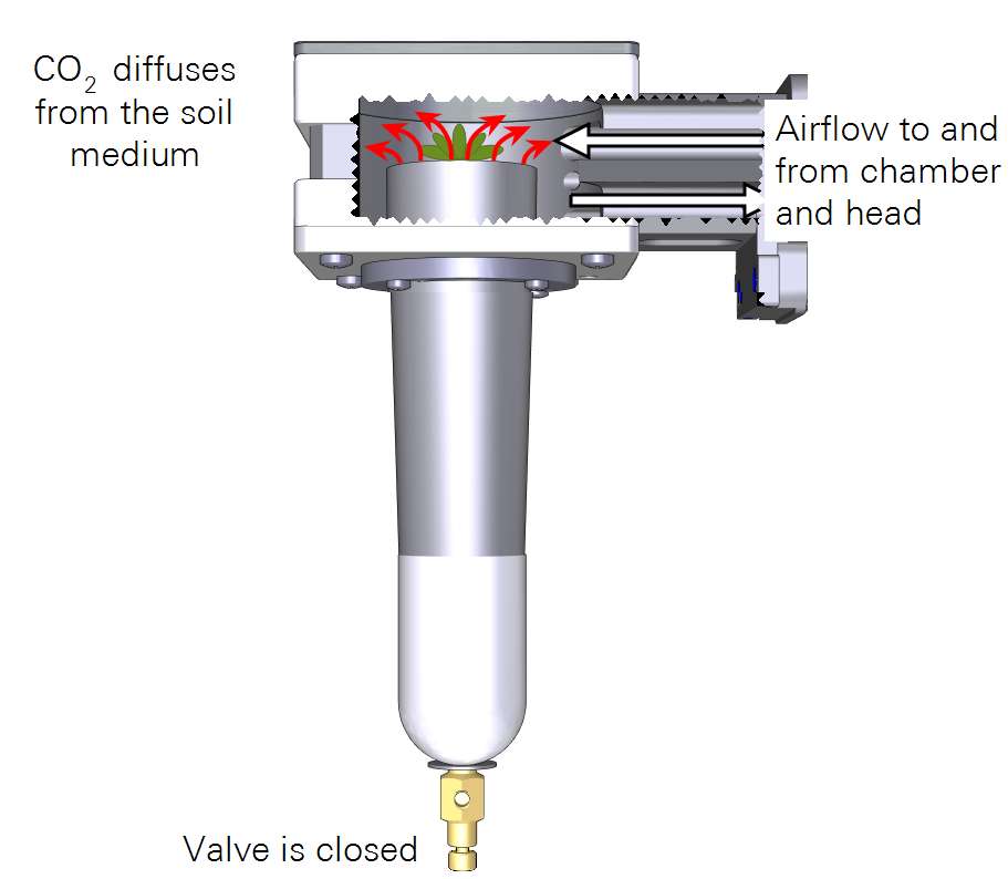
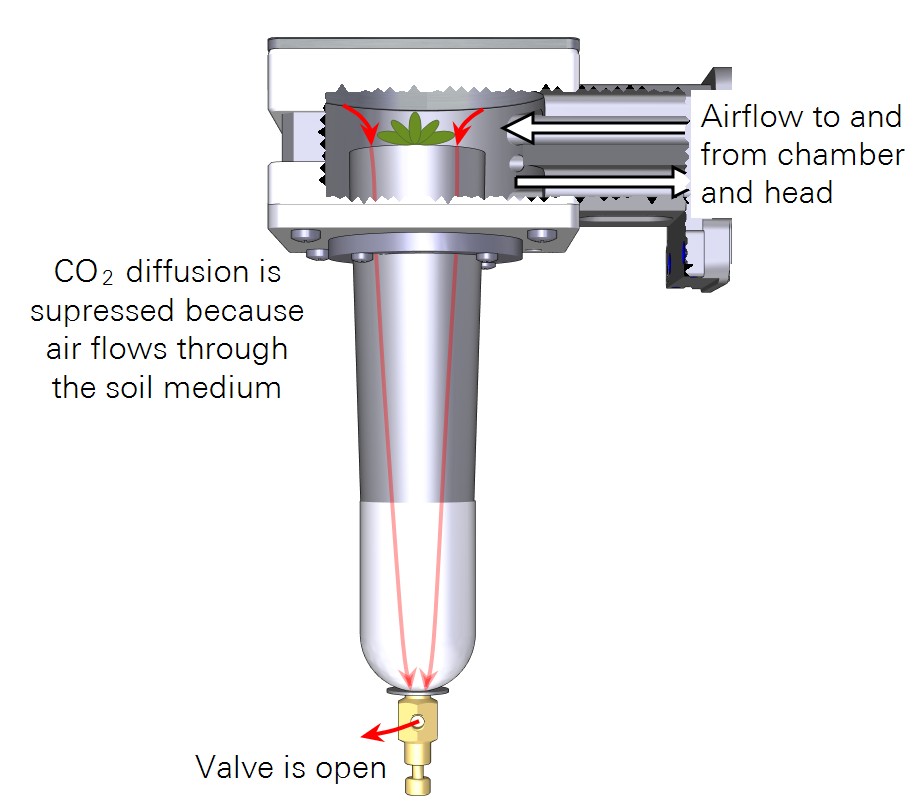
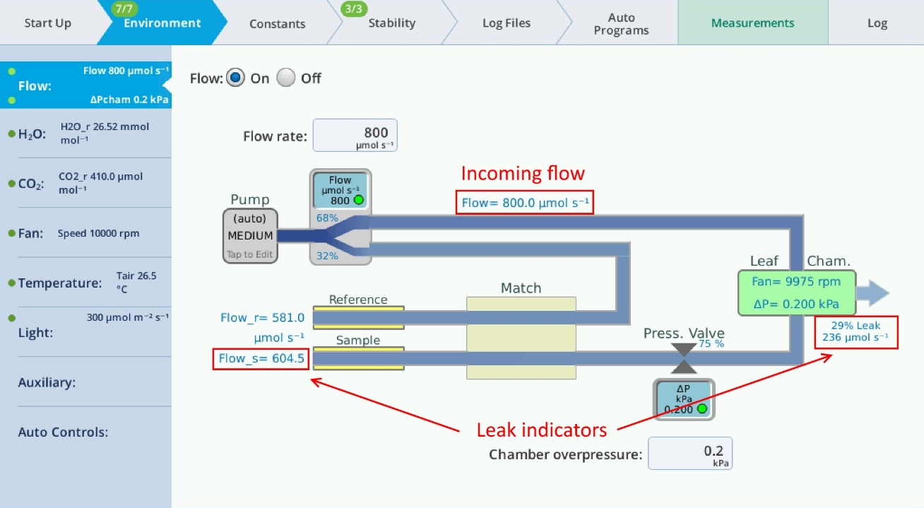
The first method takes advantage of the chamber overpressure capabilities of the LI-6800 and controlled flow leaks through the included valve assemblies in order to suppress soil CO2 flux. The problem of a no-leak flow path is shown in Figure 1‑1; the goal is to create a flow path through the valve assembly as indicated in Figure 1‑2. Place the appropriate valve assembly on the bottom of the pot or Cone-tainer prior to placing it into the small plant chamber. Then, set the chamber environmental conditions as needed for the experiment being conducted. On the console, under the Environment tab, bring up the flow control screen, and look at Flow_s as well as the leak indicator on the right side of the screen. The value of Flow_s should be equal to, or possibly greater than, the flow rate that has been previously set, and the leak indicator should read at, or close to, 0%. If it is not, make sure the valve assembly is fully closed. If it is fully closed and there still appears to be a leak, it will be necessary to address this leak before continuing.
The most common cause will be a poor seal between the plant container and the bottom gasket of the small plant chamber; another possibility is the seal between the plant container and the valve assembly. Once corrected, slowly open the needle valve until the approximate flow leakage (as indicated by the drop in Flow_s and/or the leakage indicator) is approximately 200 µmol s-1 (Figure 1‑3). The flow will then suppress CO2 flux from the soil and therefore minimize the error due to this flux.
Method 2:
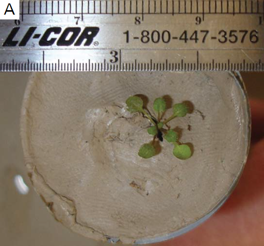
The second method involves using some kind of barrier to seal off the surface of the growing medium and therefore prevent soil CO2 from entering the measurement chamber. One successful approach uses pottery clay. An approximately 5 mm thick layer of clay is placed on top of the growth media and a small hole (approximately 6 mm) is made in the center of the clay. A seed or 5-10 day old seedling can be placed into the hole; if the growth media is kept moist, the clay will remain moist as well and will provide a suitable growth surface for the plant. As the plant grows, it will occlude the center hole in the clay and thus seal off soil CO2 from the chamber (Figure 1‑4). Another approach using petroleum jelly was found to be somewhat messier but did seal well. Plastic film, however, is not recommended since plants tended to germinate under the film and the center hole was not well sealed and allowed soil CO2 into the plant chamber.
Method 3:
If the plant being measured is not needed for seeds or further tests, then it’s possible to directly measure CO2 respiration from the growth media and roots. To use this method, the plant should first be measured with the chamber pressurization set to zero and the plant container valve assembly completely closed. In this configuration, there should be no flow leaks, which can be verified by looking at the flow leakage percent on the right side of the instrument flow control screen. After the plant and chamber have reached steady state, data can be logged. The top (vegetative) portion of the plant is excised, and another measurement is logged with the same instrument settings that were used previously. The CO2 flux (negative assimilation rate) is then subtracted from the measurement taken with the whole plant, which results in higher assimilation rates after the correction. Note that when removing the vegetative part of the plant, it is advisable to work in a way that disturbs the growth media as little as possible in order to minimize perturbation of growth media CO2 flux.
Chamber pressurization testing results
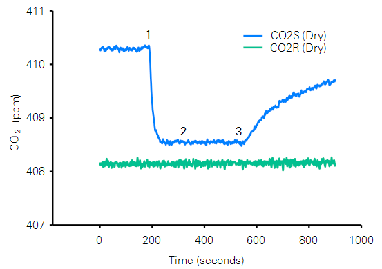
Results from a typical experiment using chamber pressurization to drive a flow leak through the Cone-tainer valve assembly are shown in Figure 1‑5. A 4 cm Cone-tainer with well-watered potting soil was placed in the small plant chamber and allowed to equilibrate for 60 minutes. The LI-6800 was set to a flow rate of 800 µmol s-1, CO2 was controlled on reference at 400 µmol mol-1, H2O was controlled on reference at 20 mmol mol-1, and the mixing fan was set to 10,000 RPM. Initially, the chamber pressurization system was turned off and the Cone-tainer valve assembly was fully closed. After 180 s, the chamber pressurization system was set to 0.2 kPa and the valve assembly was opened to allow for approximately 200 µmol s-1 flow leakage. At 360 s, the valve assembly was further opened to increase to leak rate to approximately 600 µmol s-1, and the valve was completely closed and chamber pressurization turned off at 540 s. Results are shown in Figure 1‑5. There was a rapid drop in chamber CO2 from approximately 410.3 to 408.5 ppm as a result of initially opening the valve to allow for 200 µmol s-1 of flow leakage, but increasing the leakage rate to 600 µmol s-1 did not result in any further chamber CO2 changes.
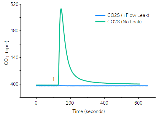
Injection experiments with pure CO2 were also conducted to test the effectiveness of the chamber pressurization system in mitigating soil CO2 flux. Here, a small hole was drilled into the side of a 4 cm Cone-tainer and 400 µL of pure CO2 was injected into the potting mix using a syringe. Results from a typical experiment are shown in Figure 1‑6. When the chamber pressurization system was turned off and no bulk flow leakage occurred through the Cone-tainer valve assembly, the CO2 injections resulted in a spike in chamber CO2 greater than 100 µmol mol-1. When the chamber pressurization was turned on and the valve assembly was opened to allow for a 200 µmol s-1 bulk flow leak, the CO2 injection resulted in a chamber CO2 spike of less than 1 µmol mol-1.
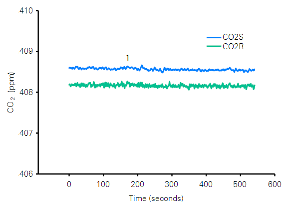
An experiment was then conducted whereby a clay cap was placed over the 4 cm Cone-tainer. The instrument settings remained the same as the ones specified previously. After 180 s, the chamber pressurization system was turned on and the valve assembly was fully opened. Results are shown in Figure 1‑7. The system flow meters indicated that the clay cap eliminated bulk flow leaks through the Cone-tainer even with the valve assembly fully open. Thus, plant chamber CO2 levels remained constant throughout the experiment. Taken together, the results from these experiments demonstrated some important operational considerations: (1) bulk flow leakage through the Cone-tainer resulted in a measurable effect in chamber CO2 mole fraction by suppressing soil CO2 flux; (2) the lack of an apparent effect of increasing the leakage rate from 200 to 600 µmol s-1 suggested that a modest leak rate was sufficient to fully suppress soil CO2 flux; (3) CO2 injection experiments revealed that bulk flow leakage could nearly fully suppress even substantially larger CO2 gradients; and (4) capping the Cone-tainer with pottery clay produced similar results, which indicated the effectiveness of both methods in controlling soil CO2 flux.
Some additional experiments were conducted to investigate the effectiveness of using chamber pressurization to control soil CO2 flux from a 6.5 cm pot. Instrument settings were again identical to those previously reported. The chamber pressurization system was turned on and set to 0.2 kPa at 120 s and the valve assembly was opened to allow a 200 µmol s-1 bulk flow leak through the pot valve assembly. At 300 s, the valve was opened further to allow for approximately 600 µmol s-1 of flow leakage through the pot, and at 480s the valve assembly was fully closed and chamber pressurization was turned off. Results are shown in Figure 1‑8.
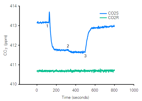
Upon opening the valve, the 200 µmol s-1 bulk flow leak decreased chamber CO2 from 413.2 to 411.7 µmol mol-1. Increasing the bulk flow leak to 600 µmol s-1 further decreased chamber CO2 to 411.6 µmol mol-1, which indicated that a 200 µmol s-1 leak rate may not have fully suppressed the soil CO2 flux. Other experiments using 6.5 cm pots (not shown) did not show a further drop in chamber CO2 concentration when the leakage rate was increased. Thus, in some cases, larger bulk flow leaks may be needed to control soil CO2 flux in 6.5 cm pots. Users may need to determine the appropriate bulk flow leak rate for themselves or use potting clay to avoid the issue altogether when using 6.5 cm pots.
Of the above methods for controlling growth media and root CO2 flux, users will need to experiment and decide what method works best for them. In some cases, the growth media may not be porous enough to allow for sufficient bulk flow leakage through the valve assembly and a method other than exhaust flow (Method 1) will be needed. For instance, we’ve previously noted that water saturated peat may effectively prevent any flow, which necessitates another approach.
Note that in many cases, there may remain a small difference between reference and sample CO2 (dry mole fraction basis) even if sufficient flow is exhausted through the pot valve assembly or if pottery clay seals off the soil flux. This small difference, usually on the order of about 0.5 ppm CO2, is seen most prevalently when a large difference in reference and sample water mole fractions exist. This is likely due to one or more of the following: (1) diffusion or bulk flow leak; (2) CO2 is coming from the water carbonate system; or (3) small imperfections in IRGA cross sensitivity corrections.
If desired, the small delta CO2 can be corrected for by running several “blanks” whereby a Cone-tainer or pot, filled with growth media and using Method 1 or Method 2 for soil CO2 flux control, are measured under conditions identical to ones used for pots with actual plants. The resulting average CO2 delta can then be used for correcting plant assimilation data. Another approach is to set reference water mole fraction to a relatively high value, so that chamber relative humidity is at or a little above 80%, which helps to reduce the overall difference in water mole fraction between reference and sample air.
Temperature, water vapor control, fan speed, flow, and leaf area
Temperature
The LI-6800 temperature control will allow for the system to maintain ambient temperatures when the small plant chamber is used outdoors in most environments. In a laboratory setting, ambient temperatures can be maintained, and some air temperature control (a few degrees) is possible, although reaching a setpoint will be slow due to chamber thermal mass. Tair or Txchg are the available control types.
Water vapor
For water vapor, it’s useful to keep in mind that water vapor will be coming from the growth media as well as the plant canopy through transpiration. Combined, these two water sources can limit the lower bound of attainable water vapor concentration in the chamber. However, operating at a higher relative humidity helps minimize water vapor concentration differences between the sample and reference IRGA. Of the various LI-6800 water vapor control types, the type of control will depend on the experiment being conducted. For survey measurements, we recommend setting the reference H2O mole fraction. For a response curve, reference H2O mole fraction can still be used, or a chamber based control such as relative humidity or sample H2O mole fraction. Leaf VPD should be avoided as a control type.
Fan speed
The fan speed needs to be high enough to ensure good mixing. A setting of 10,000 RPM achieves this, but higher fan speeds also increase mass transport of moisture from the growth media. Lower fan speeds can be used if desired, but we don’t recommend a speed less than 5,000 RPM because chamber mixing becomes questionable below this threshold.
Flow rates
When setting flow rates, one should remember that the small plant chamber has a fairly large volume, and higher flow rates (600 µmol s-1 or above) should generally be used. Higher flow rates reduce the air mean residence time in the chamber, which may help control chamber moisture conditions as well as allow for faster flushing to reach steady state conditions more quickly after a new plant is placed in the chamber.
Leaf area
The main considerations are minimum leaf area requirements and how to calculate canopy leaf area. For total canopy leaf area, there should be a minimum of about 2 cm2; more leaf area will provide better signal. Calculating canopy leaf area may not be trivial, but there are a few ways this might be accomplished. If destructive techniques can be used, a leaf area meter such as the LI-3100C can be used to find the leaf area of the small plant. However, if destructive techniques need to be avoided, then taking a picture of the plant followed by analysis in image processing software, such as the freely-available Image J (https://imagej.nih.gov/ij/), can be used to obtain leaf area. Several explanatory videos are available on the Internet for those who are interested in using this technique.
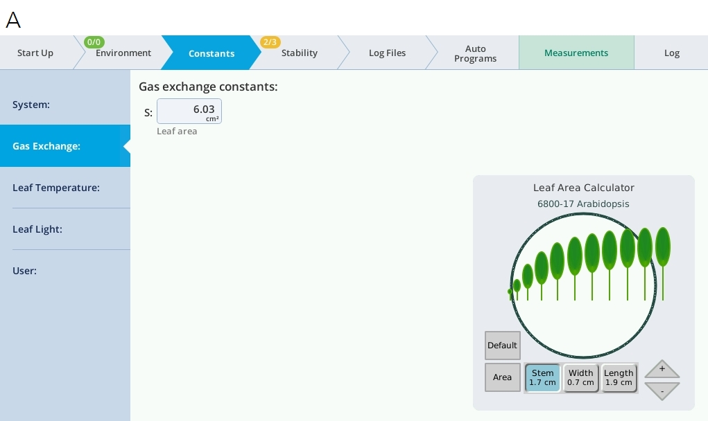
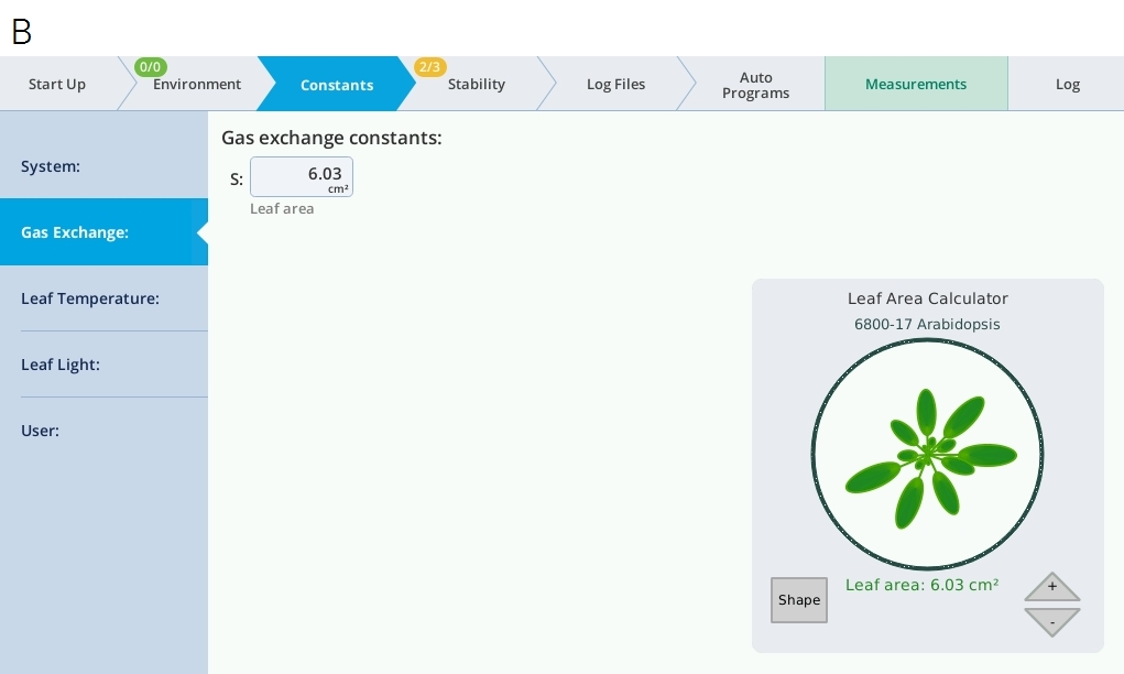
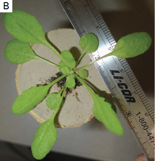
For Arabidopsis researchers, the LI-6800 has an Arabidopsis simulator that will provide an estimate of total leaf area. To use this tool, the maximum stem length, as well as the maximum leaf width and length, should be measured for a plant and input into the model (Figure 1‑9; A and B). The resulting “plant” can then be adjusted to mimic the approximate morphology of the plant being measured. However, keep in mind this is only an estimate of total leaf area from the model; a direct measurement is still preferable.
Conclusions
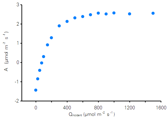
The LI-6800 Small Plant Chamber provides users the capability to make gas exchange measurements on small-stature plants or seedlings grown in 4 cm Cone-tainers or 6.5 cm small pots. The chamber pressurization system of the LI-6800, when coupled with the needle valve assembly, makes it possible to drive a quantifiable flow through the growth media in order to suppress CO2 flux, provided media porosity is sufficiently large to allow flow. Additional practices, such as clay capping, can be used to seal off media CO2 flux if chamber pressurization proves insufficient. With care and good instrument setup, typical results like the A/Q curve shown in Figure 1‑10 can be obtained.
Useful part numbers
| Part Number | Description |
|---|---|
| 610-09645 | 4 cm (1.5 inch) Cone-tainers |
| 610-09646 | 6.5 cm (2.5 inch) pots |
| 9968-261 | Valve assembly for 4 cm Cone-tainers |
| 9968-262 | Valve assembly for 6.5 cm pots |
| 6564-279 | Bottom gasket for 6.5 cm pots |
| 192-09262 | Chamber top O-ring |
| 192-05062 | Bottom plate O-ring |