
Using two light sources simultaneously
Printable PDF: Using two light sources simultaneously
(6800_InstallGuide_Light_Extension_16740.pdf)
Download this content as a pdf that can be saved to your computer or printed.
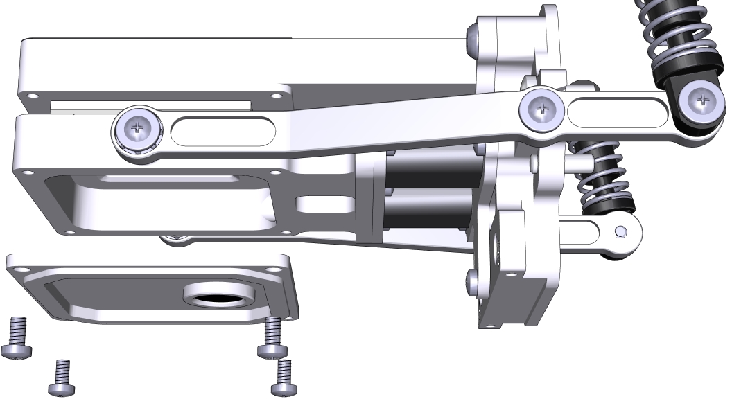
Installing Propafilm on the lower chamber
- Remove the lower leaf-temperature thermocouple plate.
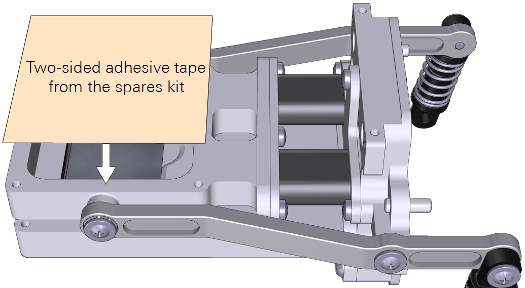
- Cut a piece of double-stick adhesive film.
- Make it 6 × 6 cm for the small chamber and about 10 × 10 cm for the large chamber. Separate one side of the film from the paper wrapper, exposing the adhesive surface.
- Press the exposed adhesive onto the lower chamber opening.
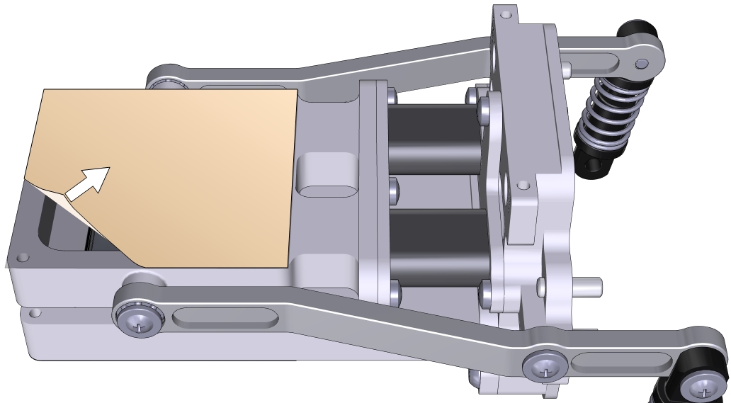
- Remove the other side of the paper wrapper, exposing the second side of the adhesive.
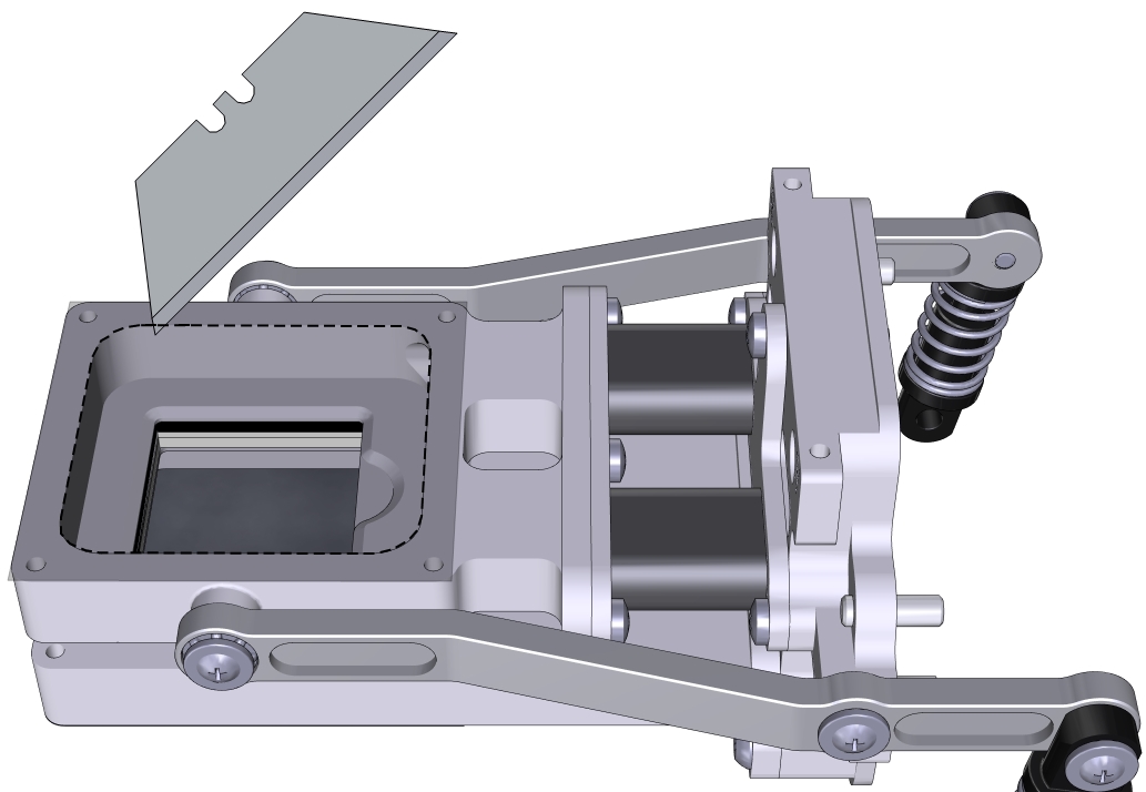
- Trim the adhesive tape from the inside of the chamber using a razor blade or a sharp knife.
- Prepare a piece of Propafilm: cut it to 6 × 6 cm for the small chamber or about 10 × 10 cm for the large chamber.
- Align one edge of the Propafilm with one edge of the adhesive. While holding the Propafilm tight, press the Propafilm onto the adhesive. Smooth any bubbles or channels in the film.
- Trim the Propafilm from around the outside of the chamber.
- Install the chamber on the LI-6800 head and run the leak test under Start Up > System Tests > Chamber Leak.
In this configuration, the chamber is a clear-top and clear-bottom chamber. You can make measurements this way if desired, or install two light sources on the chamber.
Since there is no place for a thermocouple in the chamber, the instrument will use energy balance to compute leaf temperature. You can choose an alternative temperature measurement under Constants > System Constants > Leaf Temperature Source.
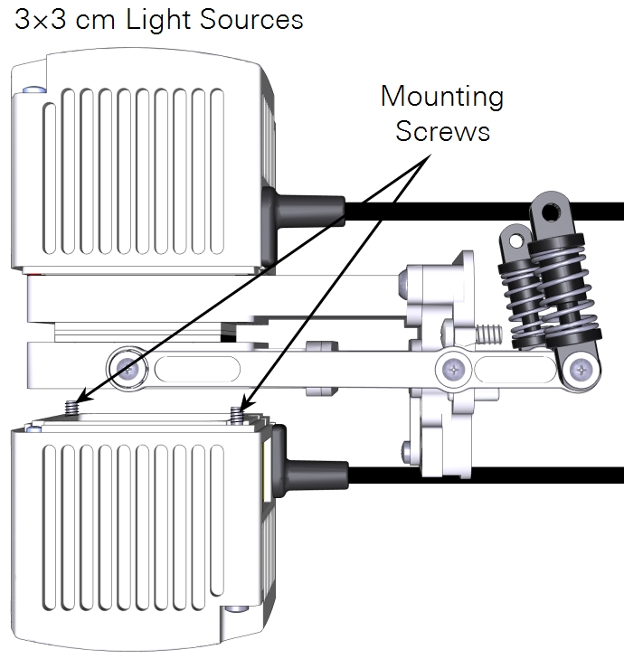
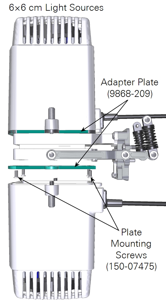
Installing the lower light source on the chamber
This procedure is slightly different for the small and large light sources. In both cases, the lower light source attaches the same way as the corresponding upper light source.
- Prepare the instrument to accept the light source.
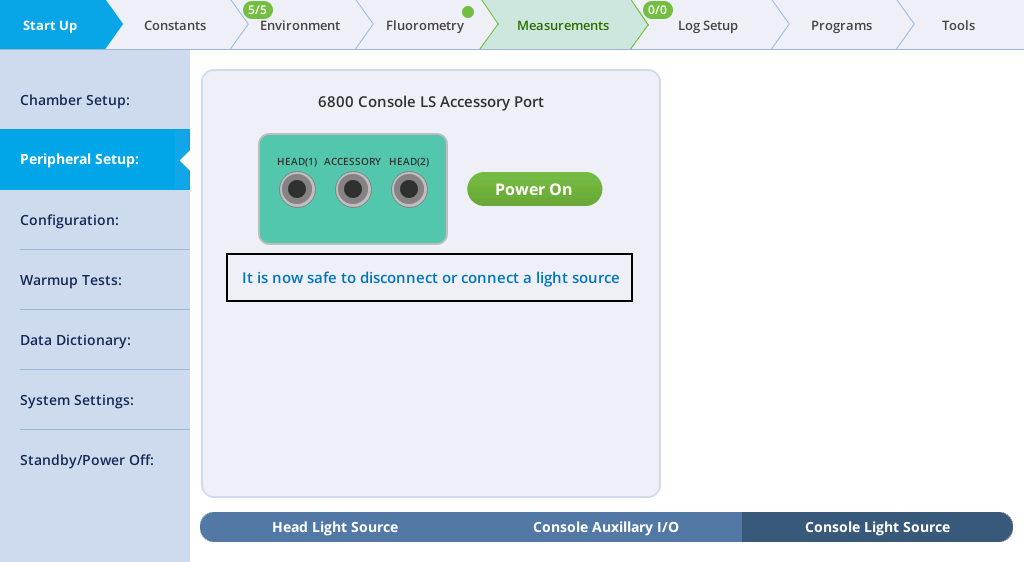
- Go to Environment > Light > Console Light Source and verify that the light source is powered off. The display will say "It is now safe to connect or disconnect a light source".
- Check the chamber Propafilm for dirt or damage.
- Clean it if necessary.
- Check the light source window for smudges or fingerprints.
- Wipe it with a soft cloth or alcohol swab if necessary.
- For the 3×3 chamber, puncture the Propafilm at the screw holes where the light source mounting screws go. Trim the Propafilm around the screw holes.
- Hold the light source in place and tighten each screw.
- The small light source attaches to the lower chamber with two screws in the corners.
- The large light source has four screws that connect an adapter plate to the chamber and two knurled screws hold the light source to the adapter plate.
- Plug the light source cable into the light source extension cable and connect the extension cable to the console connector labeled ACCESSORY.
- Secure the cable in the clasp and sheath.
- Check the light source under Environment > Light.
- When the console light source is detected, the instrument will turn Console LS on and present you with options to configure the light source.
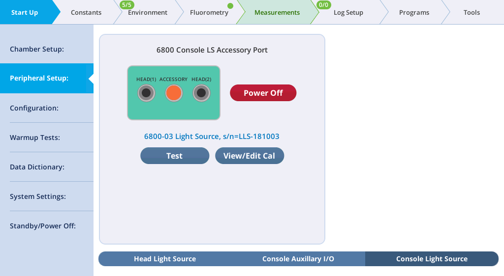
- Under Environment > Light > Console Light Source, set Control Mode to Setpoint, and set the Setpoint to 200 µmol m-2 s‑1. Open the chamber and look at the light that shines out of the chamber bottom (never look directly into the light sources).
You can control both light sources manually or automatically with an Auto Control, Program, or Background Program.
 Warning: The light sources for this product can emit potentially hazardous optical radiation (RG-2 CAUTION POSSIBLY HAZARDOUS OPTICAL RADIATION EMITTED FROM THIS PRODUCT), in excess of the Exempt Risk Group. Potential risk depends upon how one uses and installs this product. Do not operate the light source while detached from the chamber. Do not look directly into the light source under any circumstances. Operate the light sources with direct access to ambient air for cooling. Do not use the product in any manner not described in the manual.
Configuring multiple light sources
Suppose you are using the 6800-12A 3×3 chamber with a 6800-02 3×3 light source attached to the top (and connected to the LS sensor on the sensor head), and another 3×3 light source attached to the chamber bottom (remove lower plate, add Propafilm, attach light source). The bottom light source is attached to the light source connector on the console.
How to set this up? Figure 9‑66 illustrates the first part of the process—getting the light sensors attached and enabled.
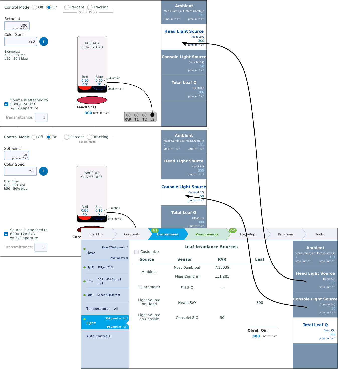
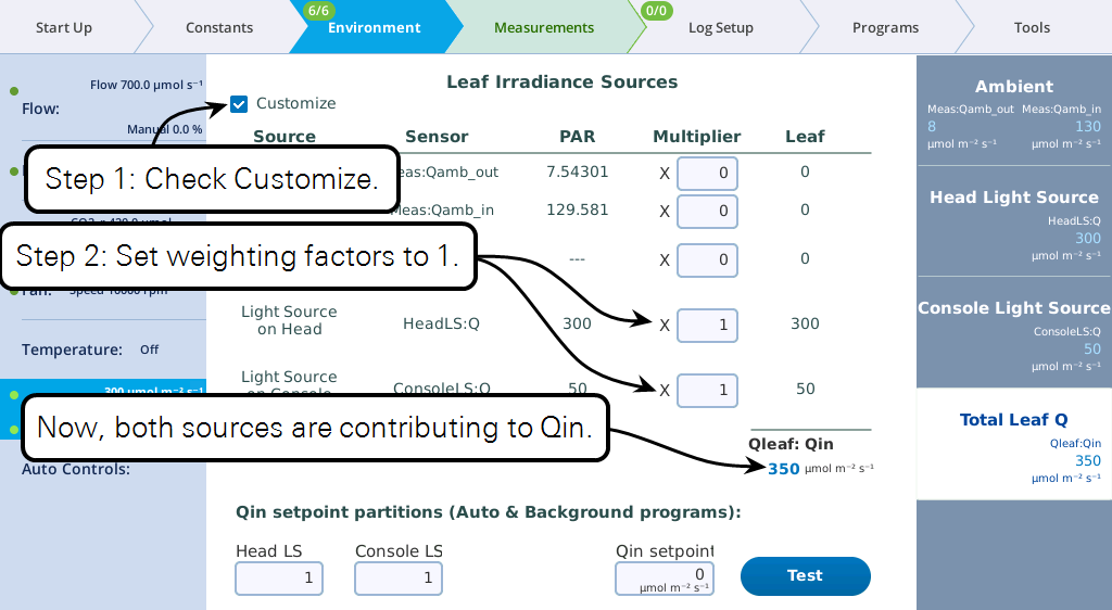
In Figure 9‑67, there are two active light sources, but the software is not yet configured to use both of them when computing the total light on the leaf. Figure 9‑67 shows how to accomplish that.
At this point, you can set the light sources independently, and their total will be Qin. But, from a program or Background Program, if you want to be able to specify Qin, with the light sources "figuring out" what their setpoints should be to achieve that, there is one more step, and that is to specify the proportions each light source should contribute (Figure 9‑68).
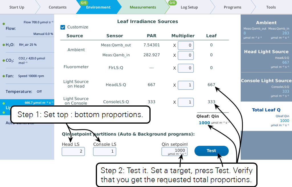
Keep in mind the following considerations regarding the values entered in the Qin setpoint partition edit boxes (i.e., Head LS and Console LS) at the bottom of Figure 9‑68
- Their values only come into play when a program or Background Program sets a Qin target, or when the Test button is pressed.
- Their values are relative. To make two light sources balance, you could enter 0.5 and 0.5, or 1 and 1, or 2 and 2, etc. To make one twice the other, you could enter 0.67 and 0.33, or 2 and 1, etc.
Keep in mind the following considerations regarding the Multiplier edit boxes visible when in Customize mode.
- They serve a multiplier that converts the light source or sensor value to the value that contributes to the leaf.
- For light sources, the values would normally be 1 or 0, depending if the source is or is not contributing to Qin. If there is a "transmittance" effect (for example, the light source is further away from the leaf than normal, or there is a customized chamber) that effect should be specified using the transmittance edit box on the light source's control screen.
- For in-chamber light sensors (or external quantum sensor), the weighting factor is the mechanism for accounting for non-standard configurations. For example, with a clear chamber top and a clear chamber bottom, one method for getting the correct total Qin would be to a) measure incoming from the top by using a multiplier of 1.0 for the internal quantum sensor, b) mount the external quantum sensor so it faces down, and c) use a multiplier for it of 0.9 to account for the bottom chamber's Propafilm.