
PDF: Using LI-6800 light sources
(6800_InstallGuide_Light-Sources_19805.pdf)
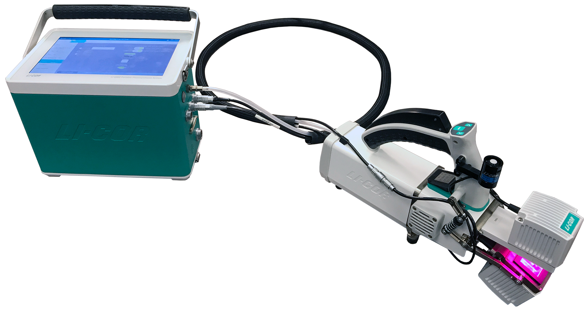
The LI-6800 features two light sources in addition to the fluorometer. These include the small light source (6800-02) for the 3×3 cm chamber and the large light source (6800-03) for the 6×6 cm chamber. Both the small and large chambers can be outfitted with one light source to illuminate one side of a leaf or two light sources to illuminate both sides of a leaf simultaneously. The latter option uses the light source extension cable (9968-243). The large leaf chamber features an optional conifer sprig adapter kit (9968-271) that can be used under ambient light, with one light source, or with two light sources. In this document, we describe how to use the small and large light sources and accessories.
What's what
Here we describe the components of each kit. You may have some or all of the components listed below.
Small light source components
Part Number 6800-02
The small light source (6800-02) is compatible with the 3×3 cm leaf chamber. It does not have a spares kit. Spare leaf gaskets and light source gaskets are included with the 3×3 cm leaf chamber.
Large light source components
Part Number 6800-03
The large light source (6800-03) is compatible with the 6×6 cm leaf chamber, small plant chamber, and the bryophyte chamber. It comes with a parts kit with the following components:
| Description | Quantity | Part Number |
|---|---|---|
| Spares Kit | 1 | 9968-249 |
| 6 mm flat screwdriver | 1 | 611-16424 |
| Light source gasket | 1 | 6568-199 |
| Screws; CSK M3×0.5; 8 mm | 4 | 150-07475 |
| Retaining washers | 2 | 144-15345 |
The large light source adapter kit (9968-189) is included with the 6×6 cm leaf chamber. It includes the following:
| Description | Quantity | Part Number |
|---|---|---|
| Adapter plate | 1 | 9868-209 |
| Screws; CSK M3×0.5; 8 mm | 4 | 150-07575 |
Light source extension cable
Part Number 9968-243
The light source extension cable (9968-243) is used to connect and operate a light source from the LI-6800 console ACCESSORY connector. With this cable, you can use two large light sources or two small light sources simultaneously.
Conifer sprig kit
Part Number 9968-271
The conifer sprig kit (9968-271) mounts directly onto the large leaf chamber. When installed, the chamber can accommodate sprigs and shoots that have leaves in a spiral arrangement. The conifer sprig kit is included with the 6800-13L sales configuration, which includes the 6800-13 large leaf and needle chamber and 6800-03 light source. The blocks can be used in ambient lighting conditions and with one or two large light sources. Be sure to use the white advanced polymer (AP) gaskets with the conifer sprig kit. The conifer sprig kit includes the following items:
| Description | Quantity | Part Number |
|---|---|---|
| Sprig adapter block | 2 | 9868-586 |
| O-rings; AS-154 Viton 175 | 2 | 192-12205 |
| Screws; PH M3×0.5; 30 mm | 8 | 150-16889 |
| Screws; CSK M3×0.5; 30 mm | 8 | 150-06115 |
Installing a light source on a chamber
Here we describe how to install either the small or large light source on the corresponding chamber.
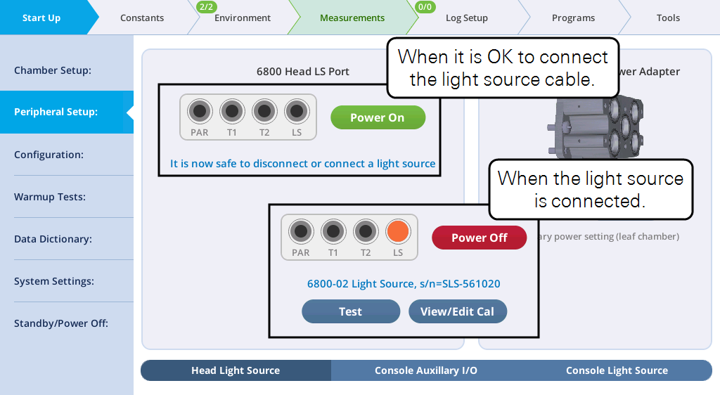
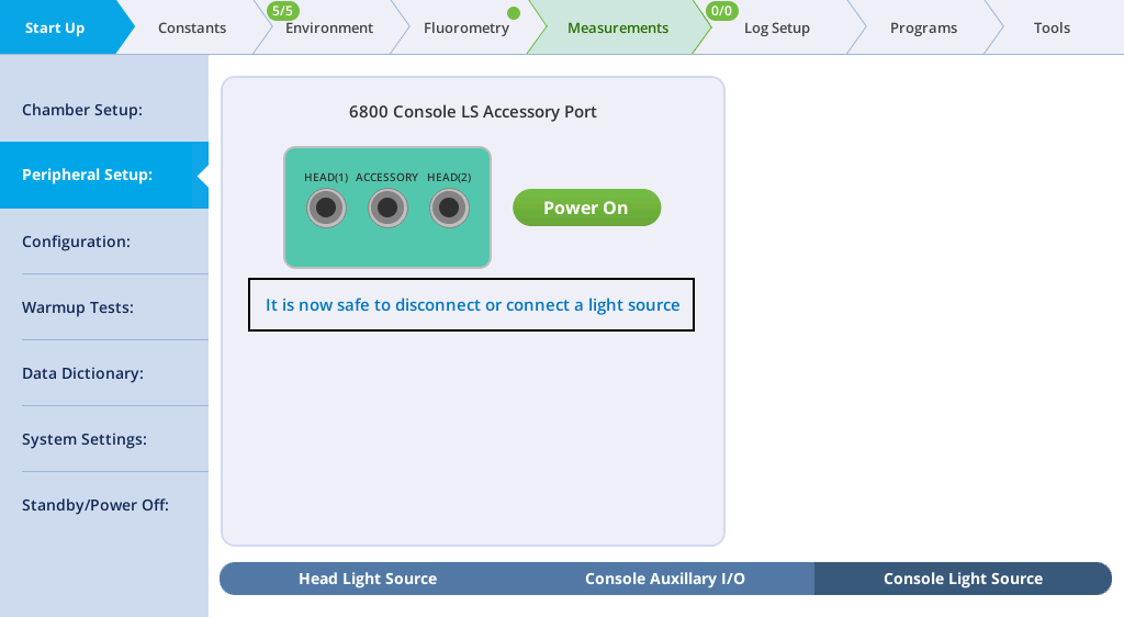
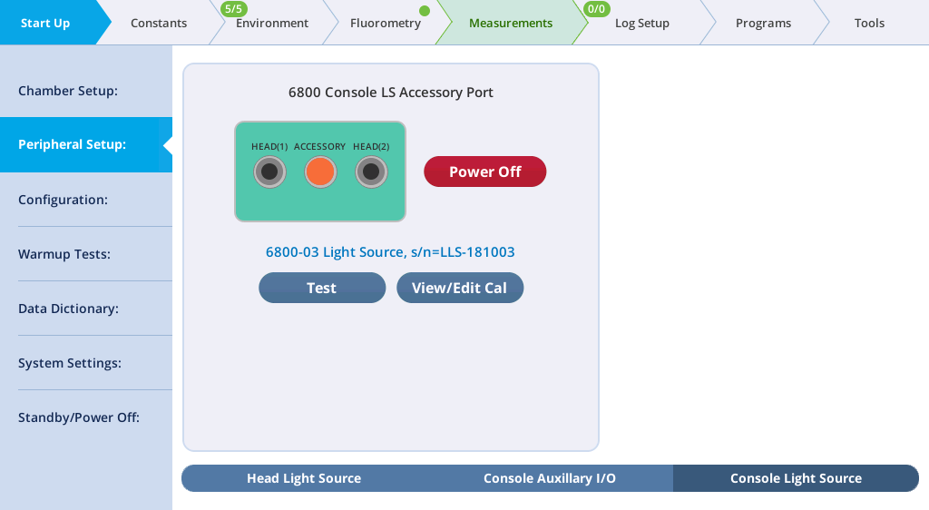
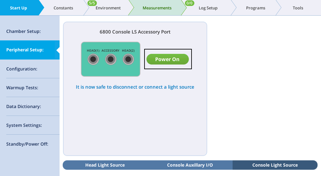
- Prepare the instrument to accept the light source. Go to Start Up > Peripheral Setup > Console Light Source and verify that the light source is powered off. The display will say "It is now safe to connect or disconnect a light source".
- Check the chamber Propafilm for dirt or damage. Clean or replace it if necessary.
- Check the light source window for smudges or fingerprints. Clean it with a soft cloth or alcohol swab if needed.
Small light source installation
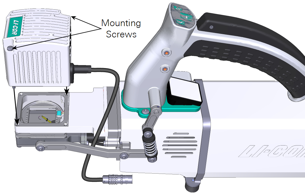
The small light source mounts directly on top of the small leaf chamber. Position the light source over the chamber and secure the two screws.
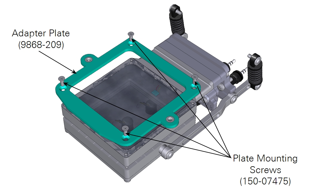
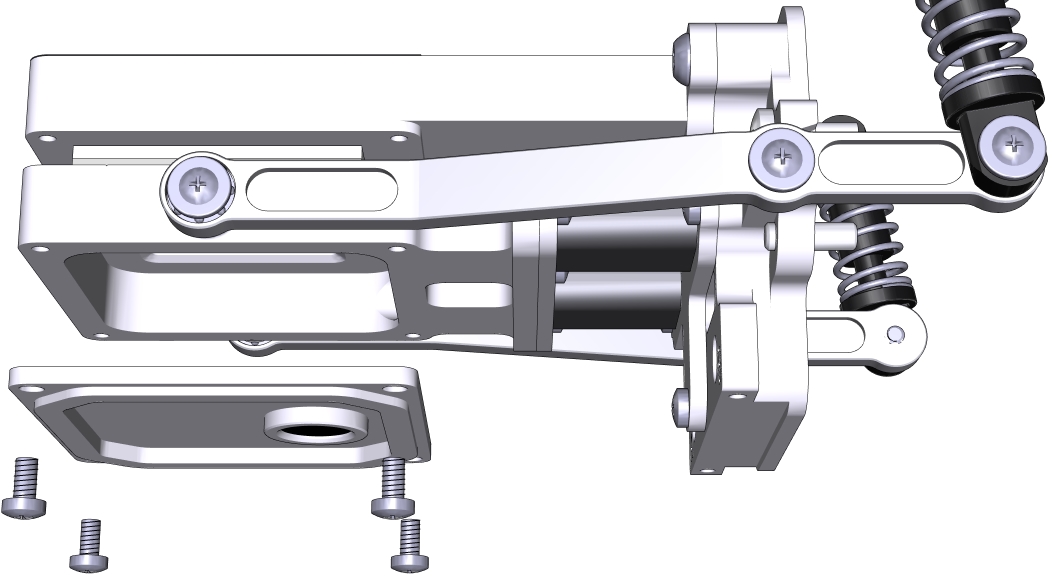
Large light source installation
The large light source mounts to an adapter plate, which is first attached to the large leaf chamber (shown), small plant chamber or bryophyte chamber.
Plugging in the cable
The light source cable connects to the head terminal labeled LS.
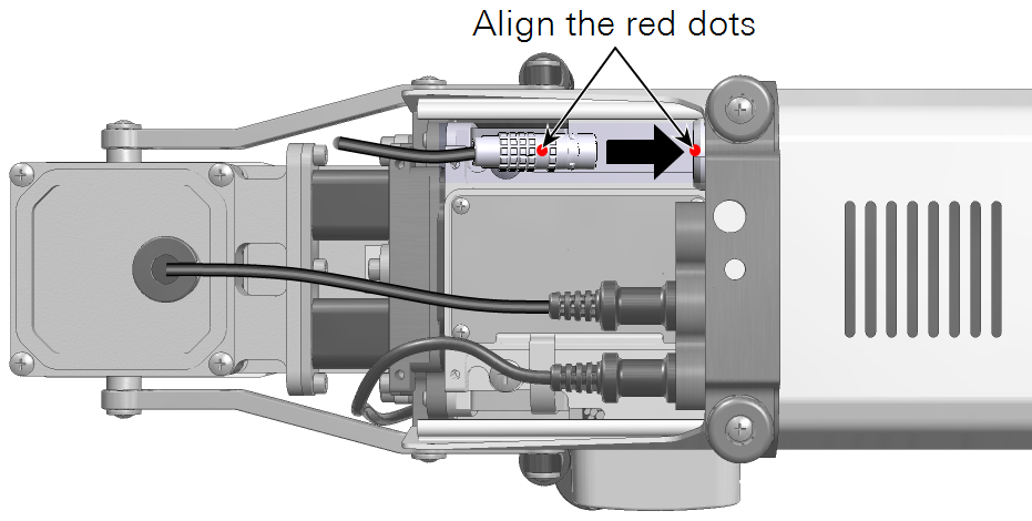
Check the light source status under Start up > Peripheral Setup > Head Light Source. It should be powered on automatically when detected. You can change the power setting by tapping the button.
Using two light sources simultaneously
Here we describe how to use the extension cable to add a second light source to illuminate both sides of a leaf in the chamber. This information applies to the small and large light sources.
Installing Propafilm on the lower chamber
The images show a 3×3 cm chamber, but the procedure is essentially the same for the 6×6 cm chamber.
- Remove the lower leaf-temperature thermocouple plate.
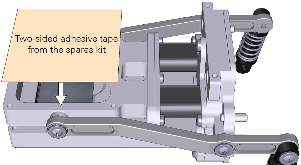
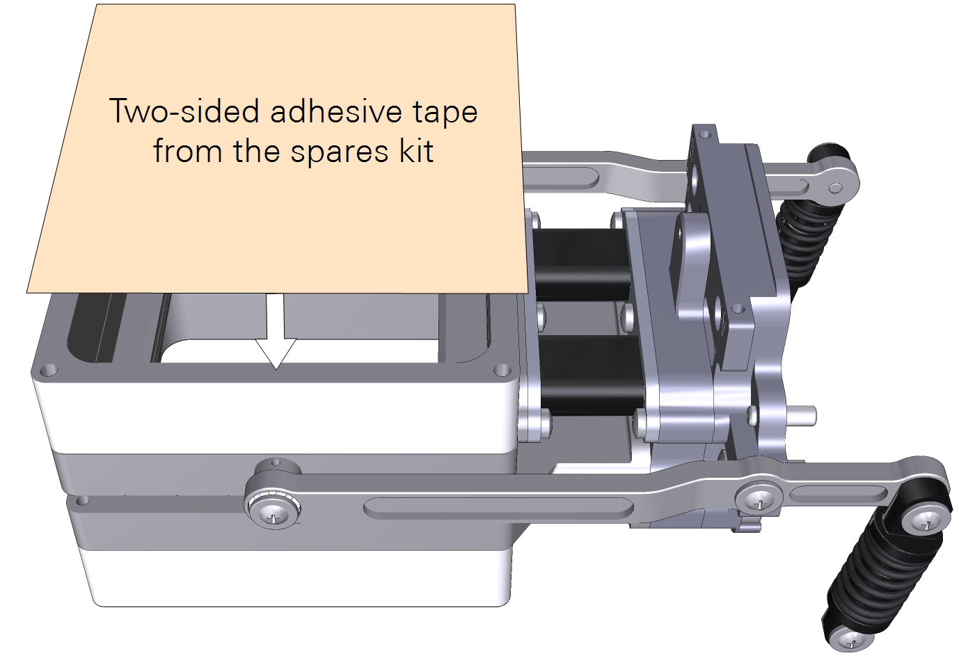
- Cut a piece of double-stick adhesive film.
- Make it 6×6 cm for the small chamber and about 10×10 cm for the large chamber. Separate one side of the film from the paper wrapper, exposing the adhesive surface.
- Press the exposed adhesive onto the lower chamber opening.
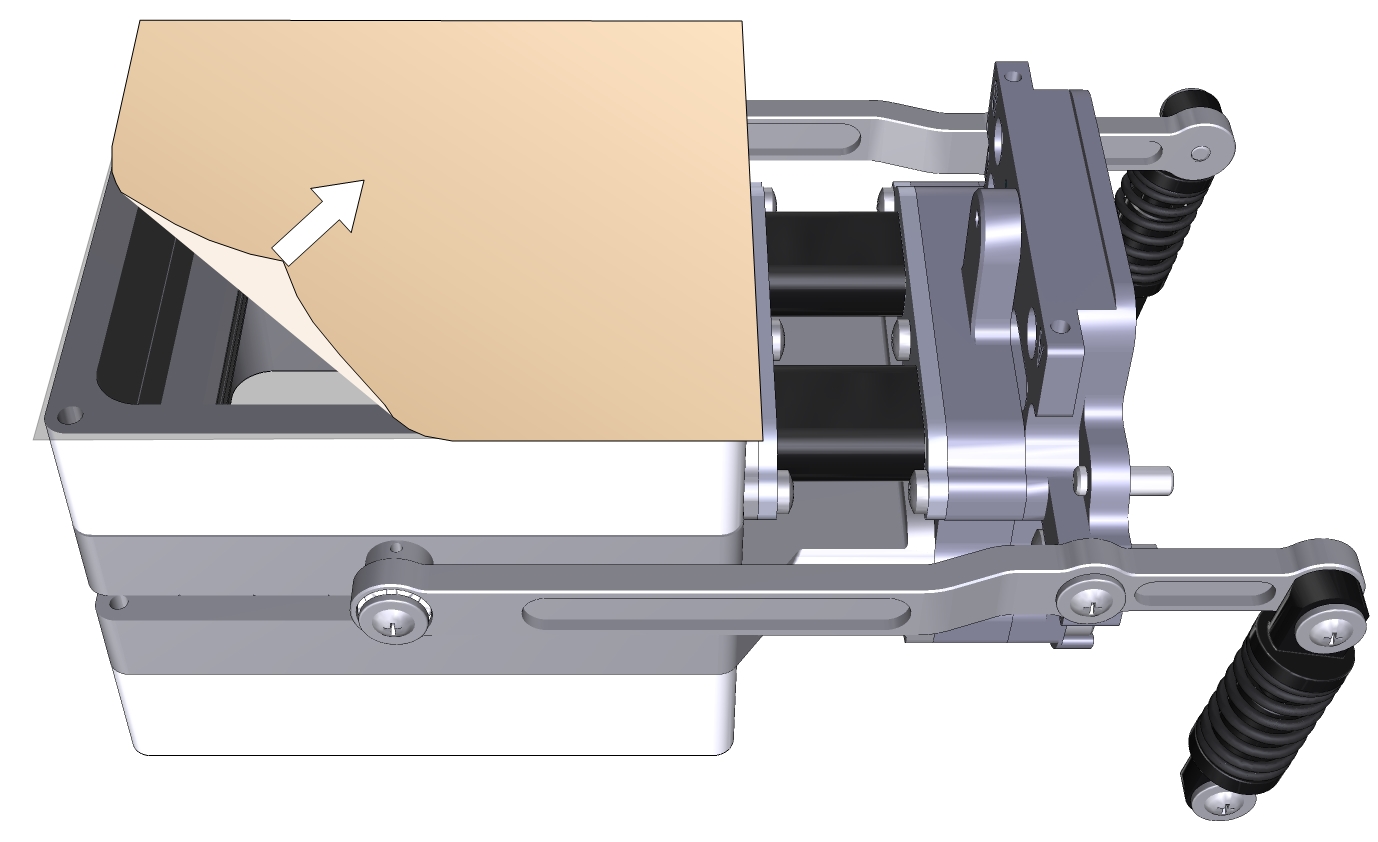
- Remove the other side of the paper wrapper, exposing the second side of the adhesive.
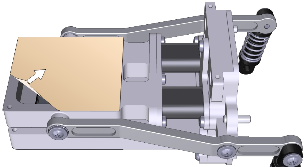
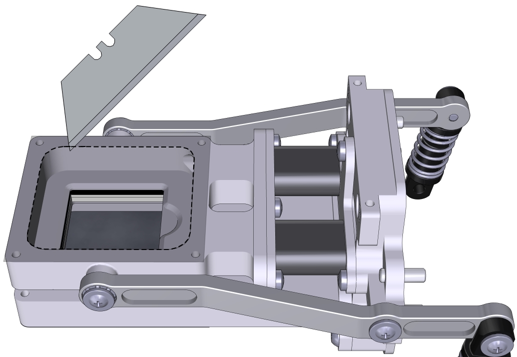
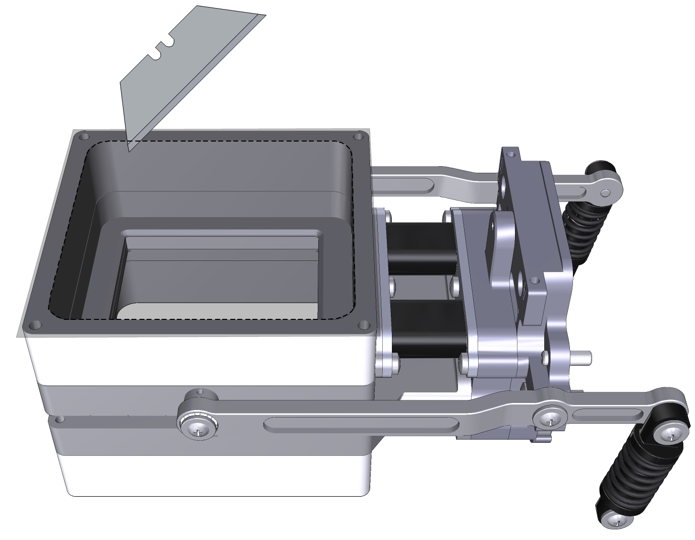
- Trim the adhesive tape from the inside of the chamber using a razor blade or a sharp knife.
- Prepare a piece of Propafilm: cut it to 6×6 cm for the small chamber or about 10×10 cm for the large chamber.
- Align one edge of the Propafilm with one edge of the adhesive. While holding the Propafilm tight, press the Propafilm onto the adhesive. Smooth any bubbles or channels in the film.
- Trim the Propafilm from around the outside of the chamber.
- Install the chamber on the LI-6800 head and run the leak test under Start Up > System Tests > Chamber Leak.
In this configuration, the chamber is a clear-top and clear-bottom chamber. You can make measurements this way if desired, or install two light sources on the chamber.
Since there is no place for a thermocouple in the chamber, the instrument will use energy balance to compute leaf temperature. You can review the settings under Constants > Leaf Temperature.
Installing the lower light source on the chamber
This procedure is slightly different for the small and large light sources. In both cases, the lower light source attaches the same way as the corresponding upper light source.
- Prepare the instrument to accept the light source.
- Go to Start Up > Peripheral Setup > Console Light Source and verify that the light source is powered off. The display will say "It is now safe to connect or disconnect a light source".
- Check the chamber Propafilm for dirt or damage.
- Clean it if necessary.
- Check the light source window for smudges or fingerprints.
- Wipe it with a soft cloth or alcohol swab if necessary.
- For the 3×3 chamber, puncture the Propafilm at the screw holes where the light source mounting screws go. Trim the Propafilm around the screw holes.
- Hold the light source in place and tighten each screw.
- The small light source attaches to the lower chamber with two screws in the corners.
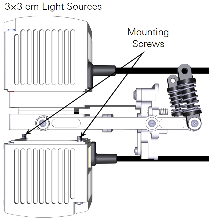
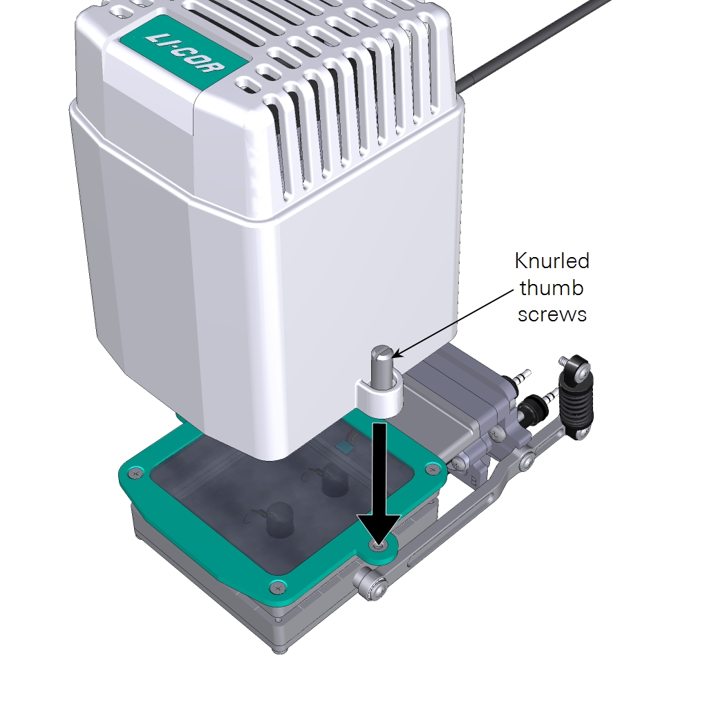
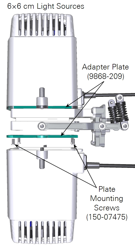
- The large light source has four screws that connect an adapter plate to the chamber and two knurled screws hold the light source to the adapter plate.
- Plug the light source cable into the light source extension cable and connect the extension cable to the console connector labeled ACCESSORY.
- Secure the cable in the clasp and sheath.
- Check the light source under Start Up > Peripheral Setup > Console Light Source.
- When the console light source is detected, the instrument will turn the light source on and present you with options to configure the light source.
- To verify the light source operation, tap the test button and proceed through the test options. Open the chamber and look at the light that shines out of the chamber bottom (never look directly into the light sources).
You can control both light sources manually or automatically with an Auto Control, Program, or Background Program.
Configuring multiple light sources
Suppose you are using the 6800-12A 3×3 chamber with a 6800-02 3×3 light source attached to the top (and connected to the LS sensor on the sensor head), and another 3×3 light source attached to the chamber bottom (remove lower plate, add Propafilm, attach light source). The bottom light source is attached to the light source connector on the console.
How to set this up? Figure 1‑1 illustrates the first part of the process—getting the light sensors attached and enabled.
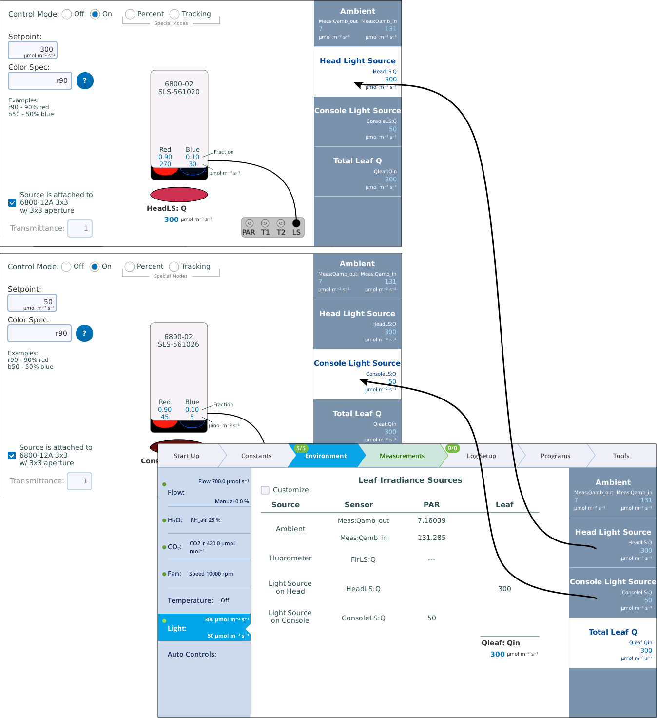
In Figure 1‑2, there are two active light sources, but the software is not yet configured to use both of them when computing the total light on the leaf. Figure 1‑2 shows how to accomplish that.
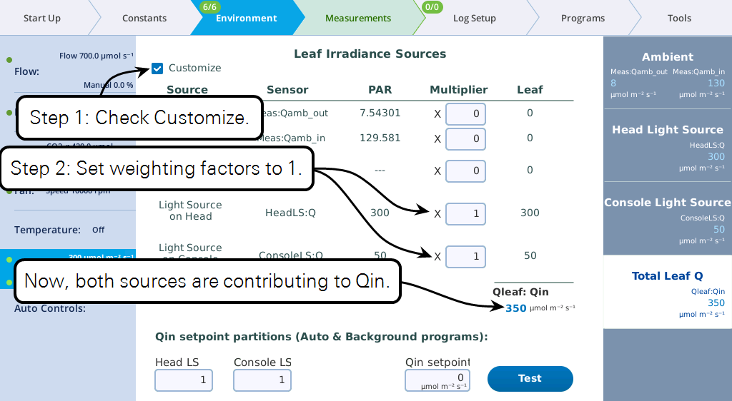
At this point, you can set the light sources independently, and their total will be Qin. But, from a program or Background Program, if you want to be able to specify Qin, with the light sources "figuring out" what their setpoints should be to achieve that, there is one more step, and that is to specify the proportions each light source should contribute (Figure 1‑3).
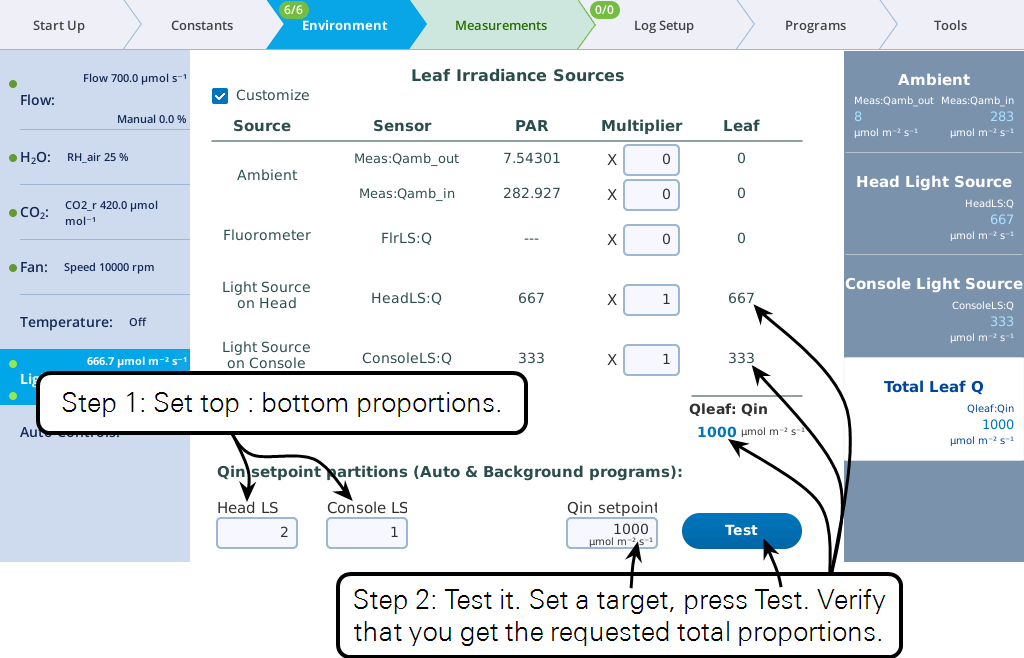
Keep in mind the following considerations regarding the values entered in the Qin setpoint partition edit boxes (i.e., Head LS and Console LS) at the bottom of Figure 1‑3
- Their values only come into play when a program or Background Program sets a Qin target, or when the Test button is pressed.
- Their values are relative. To make two light sources balance, you could enter 0.5 and 0.5, or 1 and 1, or 2 and 2, etc. To make one twice the other, you could enter 0.67 and 0.33, or 2 and 1, etc.
Keep in mind the following considerations regarding the Multiplier edit boxes visible when in Customize mode.
- They serve a multiplier that converts the light source or sensor value to the value that contributes to the leaf.
- For light sources, the values would normally be 1 or 0, depending if the source is or is not contributing to Qin. If there is a "transmittance" effect (for example, the light source is further away from the leaf than normal, or there is a customized chamber) that effect should be specified using the transmittance edit box on the light source's control screen.
- For in-chamber light sensors (or external quantum sensor), the weighting factor is the mechanism for accounting for non-standard configurations. For example, with a clear chamber top and a clear chamber bottom, one method for getting the correct total Qin would be to a) measure incoming from the top by using a multiplier of 1.0 for the internal quantum sensor, b) mount the external quantum sensor so it faces down, and c) use a multiplier for it of 0.9 to account for the bottom chamber's Propafilm.
Installing the sprig adapter blocks
The blocks can be installed on the large leaf chamber while it is attached to the head, but you may find that it is easier to install the blocks while the chamber is removed from the head.
Preparing the chamber
- Remove the Propafilm from the upper part of the 6×6 cm leaf chamber (not the sprig block).
- Puncture the film and pull it free of the top chamber. Pull carefully so that you remove as much adhesive as possible. Use rubbing alcohol to soften any remaining adhesive residue on the chamber and remove it so that the upper surface is clean. There is extra Propafilm in the chamber spares kit so you can replace the cover when you aren't using the adapter blocks.
- Remove the thermocouple plate from the bottom of the lower chamber.
- Keep the screws, plate, and thermocouples close by for re-installation.
Configuring the instrument
The sprig blocks will add volume to the chamber so under Start Up > Chamber Setup > Chamber Info, edit the volume to 418.7 cm3. The volume is used for sample cell control (CO2_s, H2O_s, RH_air, SD_air, and VPD_leaf).
If using a light source with the conifer sprig adapter blocks, under Environment > Light > Head Light Source and/or Console Light Source, clear the Source is attached to... box and change the transmittance to 0.7. A transmittance factor of 0.7 will ensure an accurate Qin at the plane of the gaskets.
Measurements with ambient light on one side
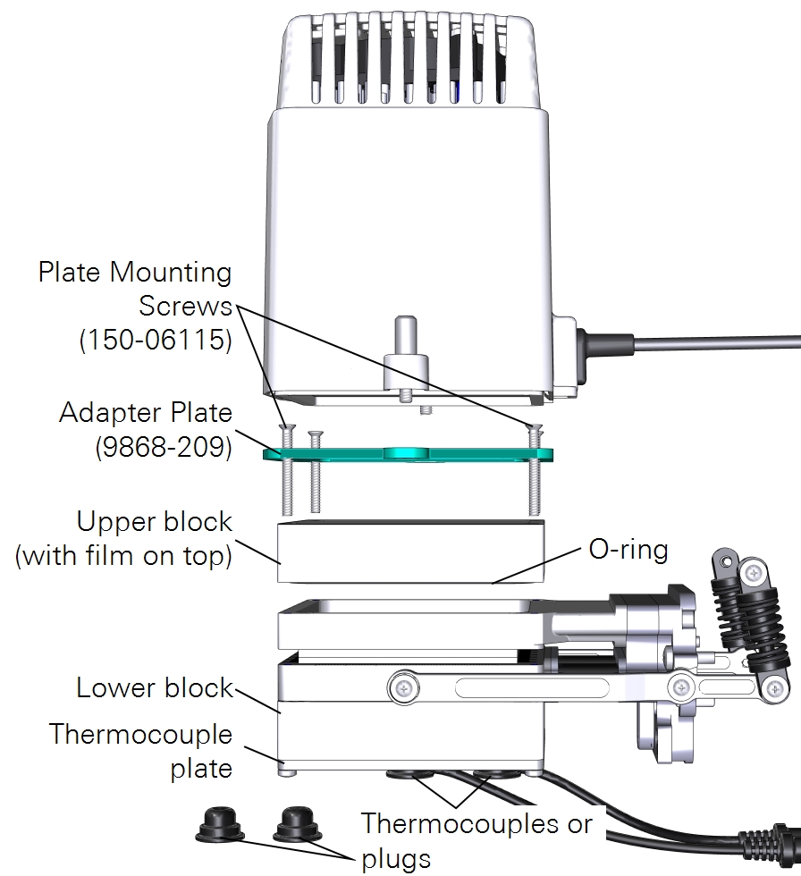
One option is to make measurements with one side of the leaf exposed to ambient light. With this measurement, the thermocouples are available to measure leaf temperature but it is unlikely that they will make contact with the sample due to the depth of the blocks. Therefore, we recommend that you use energy balance to compute leaf temperature. To install the blocks:
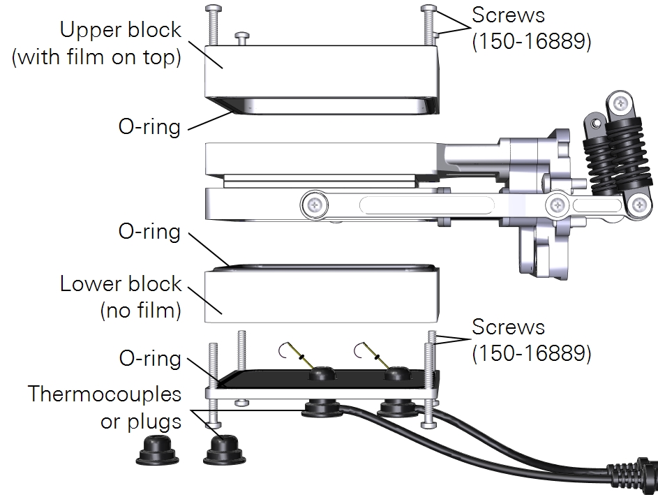
- Attach the block with film on top to the upper chamber using four panhead screws (150-16889).
- Install the thermocouples or thermocouple plugs in the thermocouple plate.
Measurements with ambient light on both sides
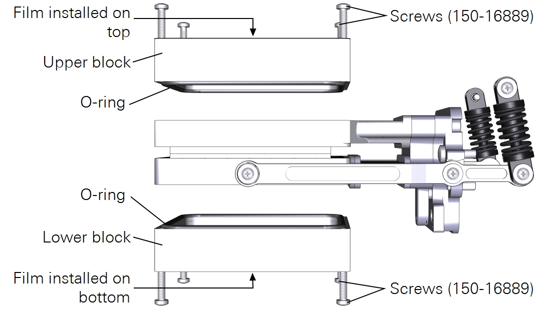
Another option is to perform measurements with ambient light on both sides of a leaf surface. For this measurement, you must remove the thermocouple mounting plate from the lower chamber and install Propafilm on the lower block. There is no leaf thermocouple available so the LI-6800 will automatically switch to energy balance to compute leaf temperature.
Measurements with a light source on one side
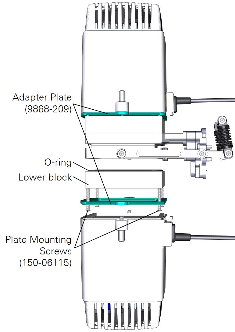
A third option is to use the large light source to illuminate one side of the leaf. Here again you can use the leaf temperature thermocouples to measure leaf temperature, but you may have better results with energy balance instead. The light source adapter plate is required to connect the light source. To install the light source:
- Attach the plate to the chamber using four countersunk plate mounting screws (150-06115).
- Pay careful attention to the orientation of the plate. The countersunk side will be in contact with the light source.
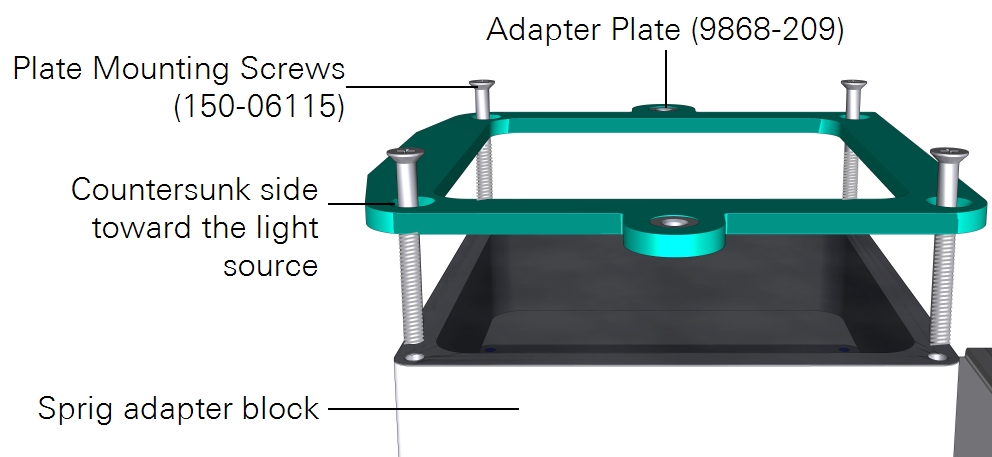
- Mount the light source to the plate with both knurled thumb screws.
- Install the thermocouples or thermocouple plugs in the thermocouple plate.
- Connect the light source cable to the LS connector on the head.
Measurements with light sources on both sides
Finally, you can illuminate both sides of the sample with two light sources. In this arrangement, you'll use the light source extension cable (9968-243) to connect one of the light sources to the console Accessory connector. The other light source cable will connect to the head LS connector. There is no leaf thermocouple available so the LI-6800 will automatically switch to energy balance to compute leaf temperature.
To install two light sources on the conifer sprig kit:
- Install the upper light source, as described in Measurements with a light source on one side.
- Install Propafilm on the bottom of the lower block.
-
- Carefully clean the surface that is accepting the film.
- Be sure that there is no film or adhesive residue remaining on the chamber. Use rubbing alcohol to soften the adhesive, if needed.
- Cut a piece of double-stick adhesive film.
- Make it about 9×9 cm for the large chamber. Separate one side of the film from the wrapper, exposing the adhesive surface.
- Press the exposed adhesive onto the chamber opening.
- Remove the other side of the wrapper, exposing the second side of the adhesive.
- Trim the adhesive tape from the inside of the chamber using a razor blade or a sharp knife.
- Prepare a piece of Propafilm.
- Cut it to about 9×9 cm for the large chamber.
- Attach the Propafilm.
- Align one edge of the Propafilm with one edge of the adhesive. While holding the Propafilm tight, press the Propafilm onto the adhesive. Smooth any bubbles or channels between the film and adhesive.
- Trim the Propafilm from around the outside of the chamber and cut the film out of the screw holes.
- Install the chamber on the LI-6800 head and run the leak test under Start Up > System Tests > Chamber Leak.
- Attach the plate to the lower chamber using four plate mounting screws (150-06115).
- Mount the light source to the plate by turning both knurled thumb screws.
- Connect one light source cable to the LS connector on the head.
- Connect the second light source cable to the console Accessory connector using the light source extension cable.
The second light source has the same options as the first light source. It is configured under the Start Up > Peripheral Setup Console Light Source.
Measuring needle-like leaves
This section describes how the sprig adapters and multiple light sources can be used when measuring needles and sprigs. The morphology of conifers and other needle species provide unique challenges for clamp-on portable photosynthesis systems. There are several techniques to make measurements on needle-type species with the LI-6800. The appropriate technique for any given experiment will depend on the goals of the proposed research.
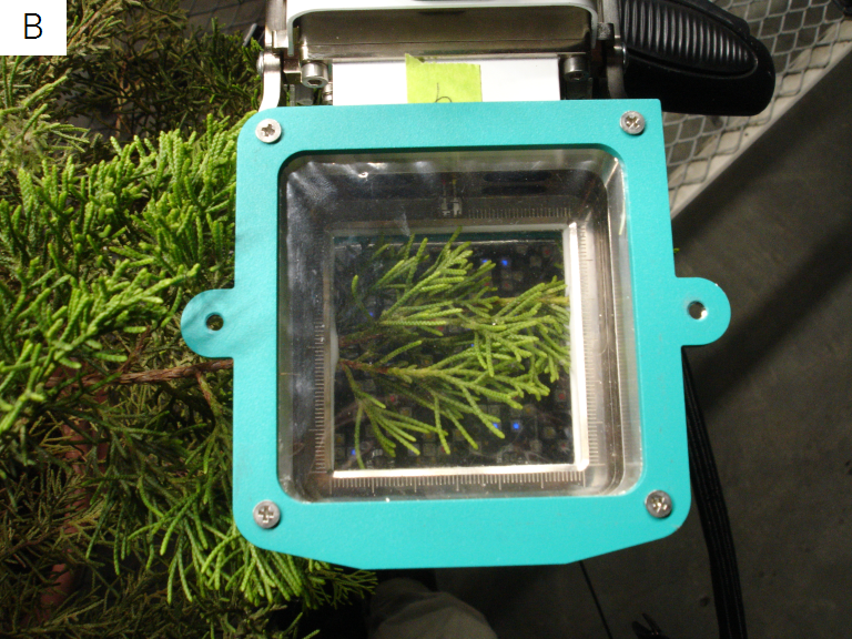
A fundamental measurement decision is to either force needles into the same plane across the cuvette (A in Figure 1‑4), or leave the sprig orientation unaltered (B in Figure 1‑4).
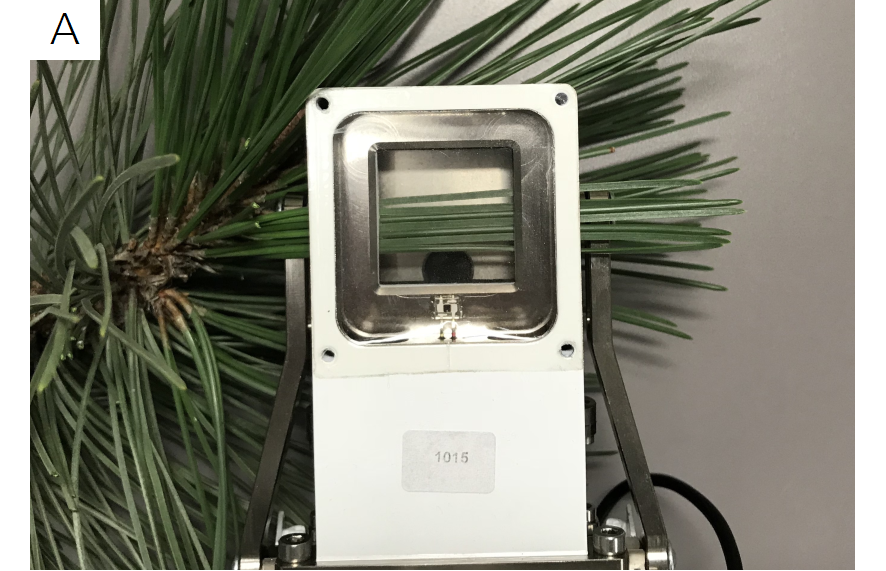
The method should be informed by the goals of the experiment and parameters of interest. Clamping on an un-altered sprig limits the parameter set to Assimilation (A) and Transpiration (E)1, with measured fluxes integrated across the entire sprig. Calculated fluxes will not necessarily reflect fluxes for any individual needle. The alternative technique of forcing needles into the same plane results in all needles in the chamber experiencing similar environmental conditions, most importantly light intensity. In this approach, an energy balance method can be used to calculate leaf temperature, allowing measurement of additional parameters including stomatal conductance (gsw) and intercellular CO2 concentrations, (Ci).
For either technique, leaf temperature cannot be measured directly by the leaf thermocouple, but is computed from energy balance (see the LI-6800 manual for energy balance computations). When measuring needles, the leaf thermocouples are not needed and should be replaced with the thermocouple hole plug (6568-523).
For both types of needle measurements, the 3×3 (6800-12A) and 6×6 (6800-13) chambers support illumination from either one side or both sides of the leaves. On either leaf surface, illumination can be from ambient light or an LED light source (Figure 1‑5).
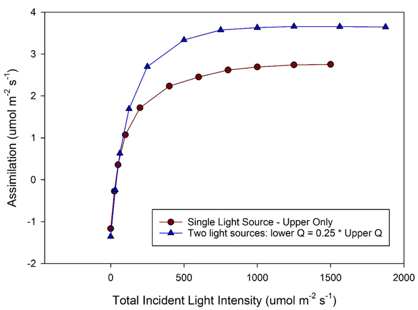
If using two light sources, each provides independent control of light intensity. The 3×3 light source (6800-02) can provide blue and red light, while the 6×6 light source (6800-03) can provide red, blue, green and white light. An example of measurements comparing a single light source to two light sources shows increased assimilation rates in a dual light source setup with 75% of total light from above and 25% below when compared to a single light source with the same total light intensity but 100% of the light from above (Figure 1‑6).
Regardless of measurement type, chamber leaks can result from clamping on needles. Several features of the LI-6800 will assist with leaks. First, the advanced polymer gaskets will conform more readily to larger needles and/or sprigs and are recommended. Second, the sample IRGA exhaust flow is monitored and a leak rate displayed for the user to monitor. Third, the LI-6800 includes a valve to maintain chamber pressure at slightly above ambient. As it is recommended to maintain a minimum sample IRGA flow of 200 μmol m-2 s-1, the amount of over-pressure can be reduced when clamping on needles to reduce chamber leaks. In many cases, that will sufficiently reduce the leak. If that is not the case, putty or poster tack can be applied to seal around the needles and mitigate leaks.
Technique 1: Needles forced to a single plane
With this technique, the available parameters include A, E, gsw, Ci, φPSII, ETR, and NPQ2. A in Figure 1‑4 shows an example of clamping on multiple needles in a single plane using the 3×3 chamber. Multiple LI-6800 chambers are appropriate for this technique including the 3×3 chamber (6800-12A), the 6×6 chamber (6800-13) for longer needles, and the fluorometer (6800-01A), which allows for additional measurements of chlorophyll fluorescence parameters, such as quantum yield of PSII (φPSII), electron transport rate (ETR), or non-photochemical quenching (NPQ).
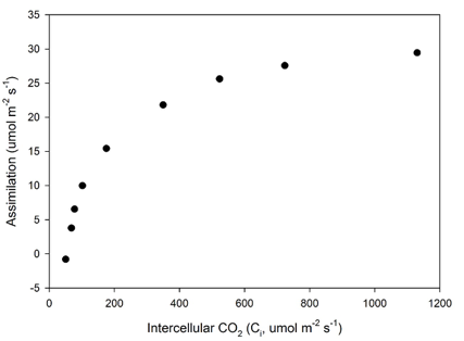
With this technique, all needles in the cuvette lie in the same plane across the chamber. Consequently, light intensity (provided either by ambient light or an LED light source) and boundary layer conductance will be uniform. Leaf temperature is then computed with built-in energy balance algorithms (see equations in the LI-6800 manual). From leaf temperature, stomatal conductance (gsw) and inter-cellular CO2 concentration (Ci) can be calculated. Leaf area in the cuvette can be calculated in several ways, with silhouette leaf area a common approach (Smith et al., 1991). Assimilation and transpiration can be computed on a leaf area basis or a mass basis. LI-6800 data files include a Microsoft Excel option with embedded equations, allowing rapid re-computation of parameters if using image analysis to compute leaf area. An example measurement of a CO2 response curve is shown in Figure 1‑7.
Technique 2: Needles left in original orientation (whole sprig)
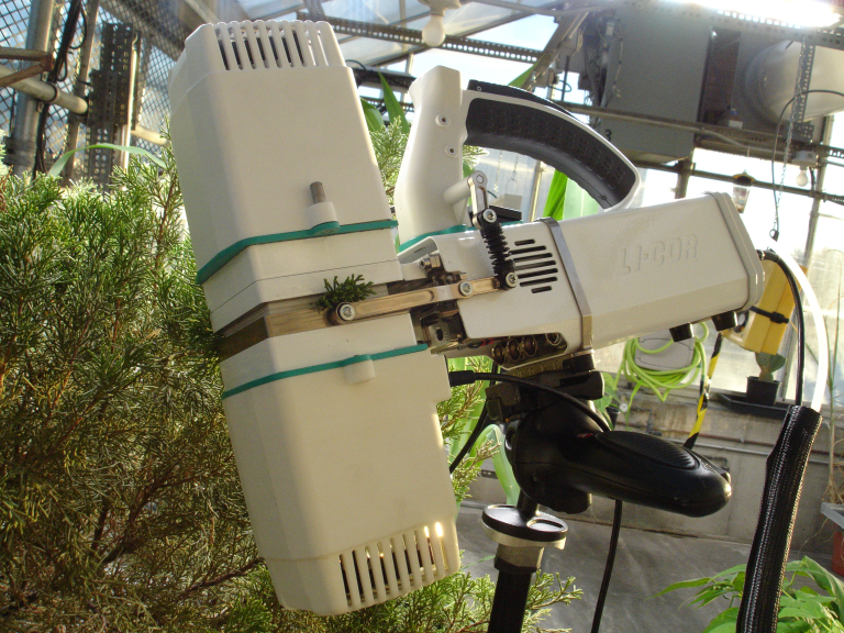
With this technique, the available parameters are A and E. B in Figure 1‑4 shows clamping on an entire sprig. The most appropriate chamber for measuring sprigs is the 6×6 chamber (6800-13) with the conifer sprig adapter blocks (9968-271). With the sprig adapters, the maximum height to the top/bottom of the chamber is 3.4 cm (1.35”).
In this approach, the individual needles remain in their original orientation on the plant and will differ in distance and angle with respect to the light source (either ambient light or an LED light source). The reported light intensity from the instrument is calibrated to the plane where the gaskets meet, that is where a planar leaf would be located when clamped. Leaf tissue departing from that plane will receive different light intensities, depending on distance and orientation from the light source. Using this technique, individual needles will likely experience different environmental conditions including light intensity and boundary layer conductance. For these reasons, needle Assimilation will likely be non-uniform across the leaf area enclosed in the cuvette. Assimilation (A) and Transpiration (E) will be an integration of all needles in the cuvette, and thus a net flux for the ‘canopy’ in the cuvette. Normalization of fluxes to leaf area can be calculated in several ways (Smith et al., 1991). Due to conditions in the cuvette and variable leaf temperature and boundary layer conductance, there will be potentially large errors in parameters gsw and Ci and they should not be trusted.
Note: Both the 6800-02 and 6800-03 have transmittance factors associated with each of the chambers to account for any losses between the lamp window and the plane of the leaf. One of the components that goes into the energy balance is the light intensity. When the leaf has a non-2D structure, the light intensity as seen by the leaf may not equal Qin, the in-chamber actinic light intensity, leading to erroneous estimates of leaf temperature as computed by the energy balance. Leaf temperature is used to calculate both Ci and gsw.
References
| 1 | Seibt, U, Rajabi A, Griffiths H, Berry JA. Carbon isotopes and water use efficiency: sense and sensitivity. Oecologia. 2008. 155: 441. https://doi.org/10.1007/s00442-007-0932-7 |
| 2 | Smith WK, Schoettle AW, Cui M. Importance of the method of leaf area measurement to the interpretation of gas exchange of complex shoots, Tree Physiology, Volume 8, Issue 2, 1 March 1991, Pages 121–127, https://doi.org/10.1093/treephys/8.2.121 |
 Warning: The light sources for this product can emit potentially hazardous optical radiation (RG-2 CAUTION POSSIBLY HAZARDOUS OPTICAL RADIATION EMITTED FROM THIS PRODUCT), in excess of the Exempt Risk Group. Potential risk depends upon how one uses and installs this product. Do not operate the light source while detached from the chamber. Do not look directly into the light source under any circumstances. Operate the light sources with direct access to ambient air for cooling. Do not use the product in any manner not described in the manual.