Resolving leaks with the
Authors: LI-COR, Inc.
Correspondence: envsupport@licor.com
Instruments: LI-6800
Keywords: chamber leaks, leak test, gaskets
Leaks usually come to your attention by causing a leak test, flow test, or pump test failure (Start Up > Warmup/System Tests), low Flow reading (mass flow to chamber), or a low Flow_s or Flow_r reading (flow through the sample/reference gas analyzer). Also, one of the following warning messages may appear on the upper left corner of the display: Console Flow Leak?, Flow_s Low, or Flow_r Low.
- If you can achieve the Flow setpoint, but Flow_s is near zero or much lower than the flow to the chamber, it is likely a chamber leak. Check the following things:
-
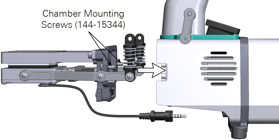
- Make sure that the chamber is installed tightly enough with two Philip screws (part number 144-15344) and adequately closed.
- Check the leaf gaskets on the chamber. If the gaskets are flattened or torn, change them. Black neoprene gaskets can recover if left uncompressed overnight, but the white foam gaskets may not. Advanced polymer gaskets recover more quickly.
| Description | Part Number |
|---|---|
| Fluorometer Gaskets | |
| 6 cm2 white foam gasket | 6568-436 |
| 6 cm2 black foam gasket | 6568-413 |
| 2 cm2 white foam gasket | 6564-202 |
| 2 cm2 black foam gasket | 6564-196 |
| 6 cm2 advanced polymer gaskets | 6568-512 |
| 2 cm2 advanced polymer gaskets | 6568-566 |
| Clear-top small leaf chamber gaskets | |
| 3×3 cm white foam gasket | 6568-429 |
| 3×3 cm black foam gasket | 6568-384 |
| 2×3 cm white foam gasket | 6564-156 |
| 2×3 cm black foam gasket | 6564-028 |
| 1×3 cm white foam gasket | 6568-584 |
| 1×3 cm black foam gasket | 6568-583 |
| 3×3 cm advanced polymer gaskets | 6568-511 |
| 2×3 cm advanced polymer gaskets | 6568-562 |
| 1×3 cm advanced polymer gaskets | 6568-560 |
| Large leaf chamber gaskets | |
| 6x6 cm white foam gasket | 6568-463 |
| 6x6 cm black foam gasket | 6568-210 |
| 6x6 cm advanced polymer gaskets | 6568-513 |
-
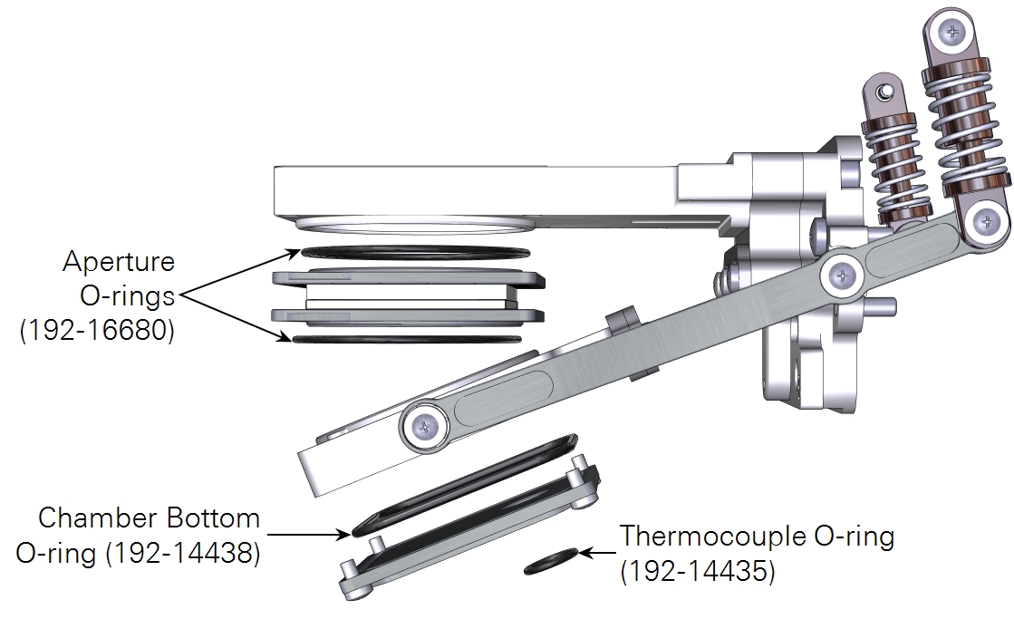
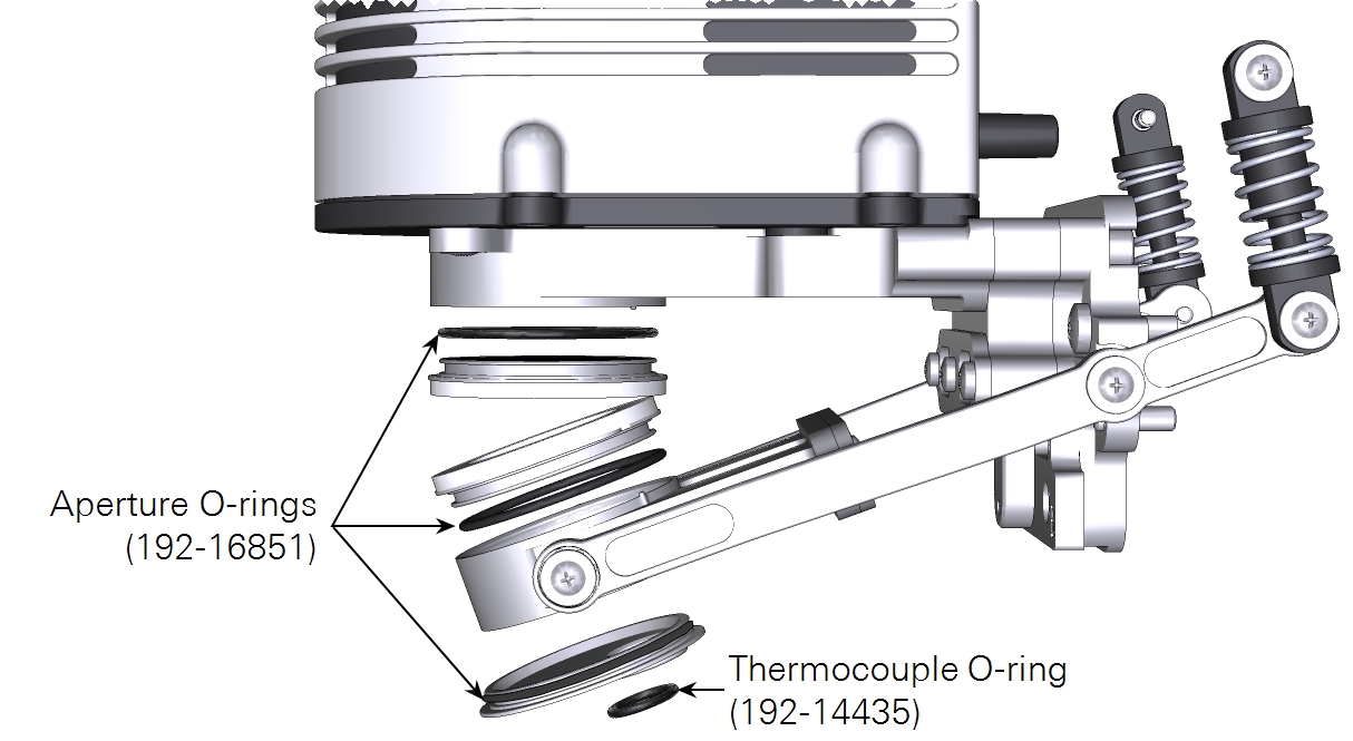
- Make sure that the thermocouple is installed and the O-ring (part number 192-14435) on the chamber bottom that seals the thermocouple is in place.
- The lower chamber may have two flexible black ducts (depends on chamber type, part number 6368-345). They may wear out over time. Change if necessary. Damage to the ducts should rarely happen, but if they are kinked during removal or installation, they may develop leaks. Ensure that the bead of the duct seats in the groove.
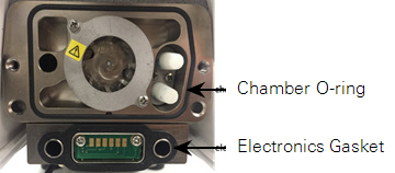
- Remove the chamber from the head and you will see the big chamber O-ring (part number 192-14438) and electronics gasket (part number 6568-327). Replace them if damaged.
- If using the leaf chambers that have the removable aperture inserts (6800-12A & 6800-01A), check if the apertures are seated firmly in the top and bottom chambers. Make sure the aperture O-rings are in place and good condition.
-
- Change the chamber overpressure (ΔP) setting (Environment > Flow) to 0 kPa or 0%. If that results in an increase of the Flow_s or decrease of the percentage of apparent leak, run the Pressure Valve test under Warmup Tests. If the test fails, contact LI-COR.
- If Flow_s / Flow_r is low and Flow cannot reach its setpoint, check the following:
-
- Make sure the humidifier and desiccant columns (part number 9968-225) are present and securely attached to the console (they should be removed during transportation and storage). Check if there are any cracks in the walls of the chemical columns.
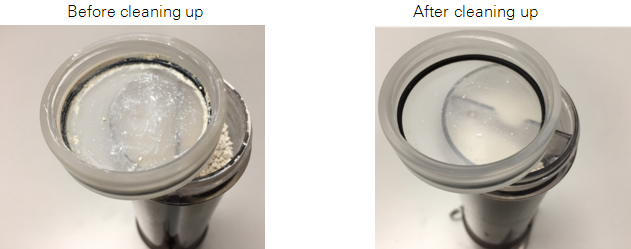
- Check to see if any chemical debris or anything else has accumulated on the threads of the cap and the tube. This will prevent the cap from getting a good seal. This may especially be the case with the Stuttgarter Masse column, where difficult-to-see ceramic particulates can accumulate. Wipe the threads, rim, and O-ring with a moist paper towel to remove any debris. This will also help keep the column and cap from being damaged by the coarse debris.
-
- To isolate a leak to either the humidifier or desiccant tubes, try replacing the tube in question with the soda lime tube (the soda lime position can remain empty – it is on the vacuum side of the pump so will not cause a leak). If that fixes the leak, you have found the culprit.
- Make sure that the O-ring (part number 192-14541) inside the bottom column cap is in place.
- Each chemical column has two filters (part number 300-14319) held in place with rubber seals (part number 6368-225). Check if any of the two air filters are missing.
- Make sure that the air supply tube is securely connected to the console outlet and sensor head inlet. Hold onto the Bev-a-line tubing (not on the Quick-connect Coupler) and pull. It should not come loose. If it does, firmly reconnect it (make sure the Quick-connect Coupler is pushed in to the end until you hear a click sound). Continued failure may indicate a new Quick-connect Coupler (part number 300-07125) is needed. Check each end of the air supply tube.
- If the Pump Speed Tests fails but you cannot identify the leak, go to Environment > Flow and set the flow split to 100% with the chamber closed. Step through each of the pump speeds and register the Flow, Flow_s, and Flow_r. If, for any of the pump speeds, the following condition is true:
- Flow_r is ˜0 but Flow and Flow_s are both low, you still have a console leak.
- Flow_r is >= 50 µmol s-1, you may have a valve leak.
- Flow = 0 or 2400 µmol s-1 while Flow_s is increasing with increased pump speeds, you may have a failed flow sensor.
- Conditions B and C both require service at LI-COR.