Digital Board Upgrade Kit Installation Instructions
There are five major steps involved in the installation of the LI-7000 digital board:
- Download and save instrument calibration and configuration files, and install new LI-7000 Windows® application.
- Remove old digital board and terminal strip and replace.
- Adjust AGC (gain) potentiometers to specified values.
- Final checkout and calibration (optional).
- Reload calibration and configuration files, and initialize instrument for USB.
The digital board upgrade can be completed in about 2 hours; it requires no soldering.
What’s Included?
| Part Number | Description |
|---|---|
| 250-07701 | Back panel terminal strip label |
| 619-05291 | Static wrist strap |
| 392-07863 | Internal USB cable, 18” |
| 392-07872 | External USB cable, 6’ |
| 122-05042 | Spare case screws (6) |
| 122-00003 | Spare digital board screws (2) |
| 167-00162 | Spare digital board star washers (2) |
| 610-05901 | 3/8” nut driver |
| 122-00009 | Spare terminal strip board screws (2) |
| 167-00163 | Spare terminal strip board star washers (2) |
| 163-00136 | Spare terminal strip board nuts (2) |
| 9970-026 | Digital circuit board |
| 9970-024 | Terminal strip with attached circuit board |
| 618-07910 | CD-ROM containing V2.0 software |
What Else is Needed?
- #1 and #2 Philips head screwdrivers
- Small slotted screwdriver to adjust gain potentiometers
- Zero gas, which can be generated with a scrubber/desiccant tube
- Span gases for CO2 and (optional) H2O
- Battery source
Step-By-Step Procedure
Follow these steps to perform the digital board upgrade:
Save your instrument calibration and configuration files
- Connect the LI-7000 to a computer with the serial cable included with the LI-7000 (p/n 9975-016) as described in Section 4 of the LI-7000 Instruction Manual, and power the instrument on (AC or battery). Open the LI-7000 Windows software program (LI7000). Choose Connect from the Remote menu, select the COM port to which you are connected, and click Connect.
-
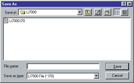
- Go to the File menu and choose Save Config, or Save Config As.... Name the instrument configuration file and save it to your computer. The instrument configuration file is automatically appended with a .l70 file extension.
-
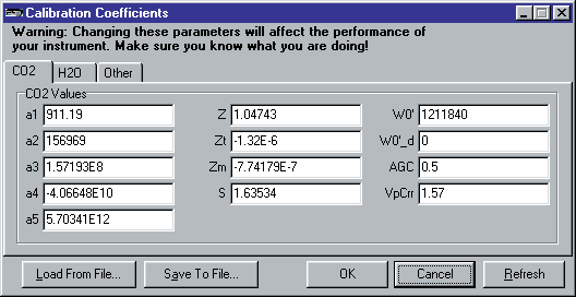
- Choose Cal Coefficients from the Configure menu. Click Save To File... Name the file and save it to your computer. The calibration coefficients file is automatically appended with a .c70 file extension.
- Choose Exit from the File menu to close the LI7000 program. Insert the CDROM included with this upgrade kit and install the Windows V2.0 software. If installation does not automatically start, select Run from the Windows Start menu, and select the Setup.exe file on the CD.
- Power the LI-7000 off, and remove the AC power cord, if you are not using battery power.
Replace the digital board and terminal strip
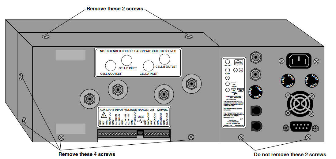
- There is a panel on the top rear of the instrument that must be removed. There are 6 Philips head screws that secure the removable panel; 2 on the top, 2 on the side, and 2 on the rear panel, as shown below. Remove the power cord and RS-232 cable. Remove the 6 screws and slide the panel straight back over the air fittings to expose the optical bench.
-
- There are an additional 16 Philips head screws on the remaining instrument cover that must be removed; there are 8 on the top, 3 on the left side panel, and 5 on the right side panel. Remove these 16 screws and lift the cover off.
- Attach the static wrist strap around your wrist, and fasten the clip to the chopper/ detector housing, as shown below. Static electricity can damage the digital board, so be sure to ground yourself in this manner before proceeding.
-
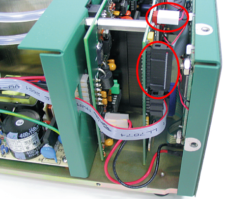
- Note the orientation, and remove the 2 LCD display connectors by pulling straight out, as shown below.
-
- There are 4 Philips head screws on the bottom of the instrument that secure the front panel. Remove these 4 screws and slide the instrument front panel away from the instrument (it is still connected via 2 connectors).
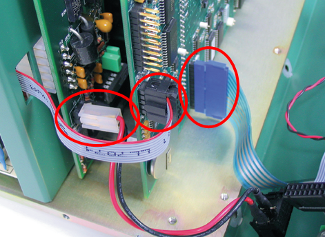
- Note the orientation, and remove the serial port ribbon connector and the blue keyboard connector, as shown below. Remove the white connector from the power switch.
-
- Remove the 8 Philips head screws that secure the old digital board with a #1 Philips head screwdriver.
-
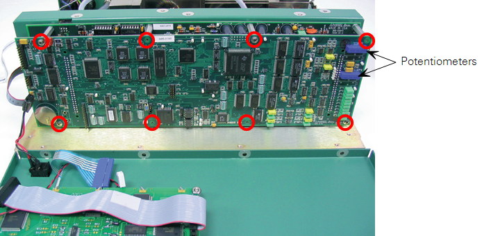
- Note the orientation of the board; the blue potentiometers shown above are on the upper right side of the board. Remove the old digital board by pulling it straight out from the 2 large connectors.
- Position the new digital board and fasten with the 8 Philips head screws removed earlier.
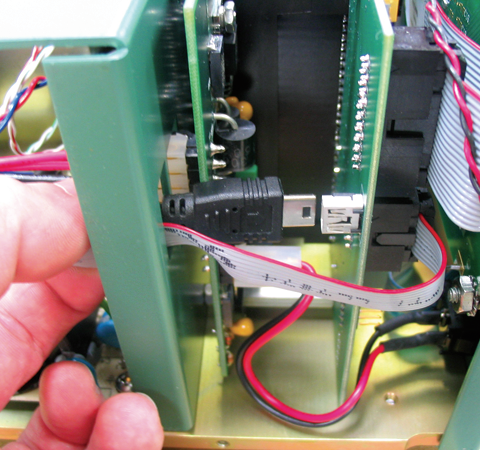
- There is a small hole in the vertical support plate that sits behind the digital boards, as shown below. Thread either end of the internal USB cable through this hole and attach the cable to the USB connector on the digital board.
-
- Reattach the 2 display connectors, the serial port connector, keyboard connector, and power connector.
- Visually verify the above connections. Make sure there are no exposed pins, and that the cable connectors are aligned correctly with the board connectors.
- Reattach the instrument front panel using the 4 screws removed previously.
- The detector and optical bench need to be removed to attach the new terminal strip board and the other end of the internal USB cable. There is a 3/8" nutdriver included with this kit that is used for removing the detector.
-
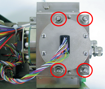
- Remove the detector and optical bench and clean the optical cell as described in Section 7 of the LI-7000 Instruction Manual, at Cleaning the Optical Cell, before proceeding. This is necessary so that the baseline gain (AGC) settings can be set using clean optical cells. Make sure the o-rings on either end of the optical cell remain in place.
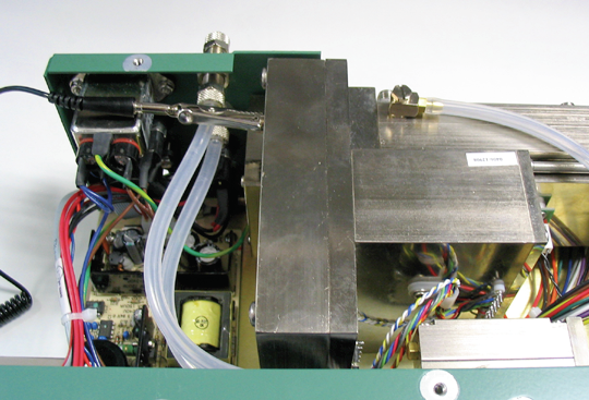
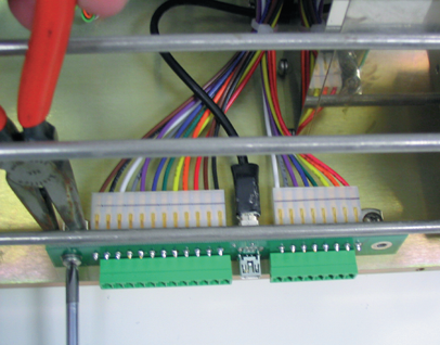
- Route the other end of the internal USB cable under the wire harnesses and air pump, as shown below.
-
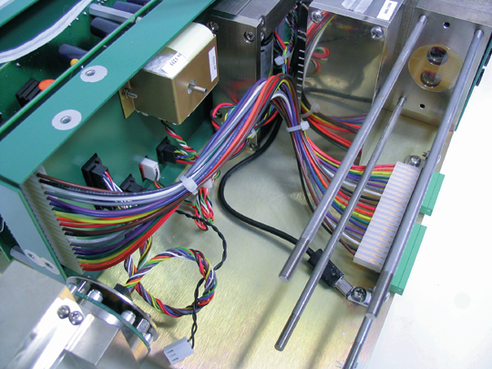
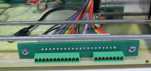
- Replace the terminal strip and attached circuit board.
-
- Mark the top of the two connectors attached to the back of the terminal strip with a line, as shown below. This will ensure the proper orientation when reattaching to the new terminal strip.
-
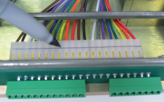
- Remove the 2 screws and attached nuts from either end of the terminal strip.
-
- Remove the 2 connectors from the back of the terminal strip by pulling straight out. Remove the old terminal strip.
-
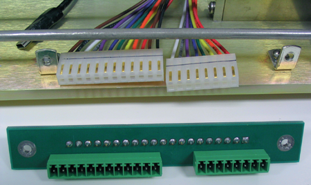
- Attach the connectors to the back of the new terminal strip.
- Insert the end of the USB cable from Step k above into the USB connector on the back of the terminal strip.
- Reattach the new terminal strip with the 2 screws and nuts. You may have to hold the nuts with a pair of long-nose pliers while inserting the screws through the terminal strip board.
-
- Re-assemble the optical bench and detector. Be sure to reattach the connectors, and the Bev-a-line tubing to the pressure transducer.
Adjust the AGC (gain) potentiometers
- Attach a battery to the instrument, if you have not already done so. Do not use AC power when performing the following steps, as it poses a severe shock hazard. If you do not have a battery to power the LI-7000, do not proceed past this step!
- Display variables #42 (H2O AGC) and #43 (CO2 AGC) on the LCD display. Press Shift + 2 to view the Display group. The variables currently defined for the active display are shown. Press f1 (Edit). Use the cursor control keys to move the highlight to the variable(s) to be changed. Press f1 again. A menu of available variables appears (below).
-
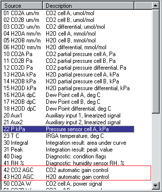
- Move the highlight to variable 42 and then 43 to display them on the LCD
- Use the PgUp, PgDn function keys, or the cursor control keys to scroll through the menu and highlight variable 42. Press f5 (OK). Repeat for variable 43. When finished, press f5 (OK).
- Make sure the LI-7000 is not in Reference Estimation Mode (REM). Plumb the instrument so that a dry, CO2-free gas is flowing through both cells A and B.
- The AGC (gain) potentiometer for H2O is located near the top right edge of the digital board as it faces you, as shown below. Use a small slotted screwdriver to turn this potentiometer until the H2O AGC value on the display reads 0.65 ± 0.1. Turn the potentiometer clockwise to raise the values, or counterclockwise to lower the values.
-
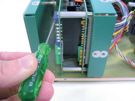
- The AGC (gain) potentiometer for CO2 is located below the H2O potentiometer, as shown above. Turn this potentiometer until the CO2 AGC value on the display reads 0.60 ± 0.1.
- Wait about 5 seconds, until “STORED” is shown on the display. Power the instrument off, remove the grounding strap, and re-assemble the LI-7000 case.
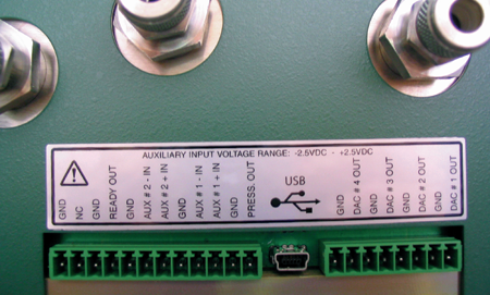
- Affix the new terminal strip label to the back panel, on top of the existing label (below).
-
Final checkout; optional with available span gases
- Connect the LI-7000 to the computer using either the RS-232 or USB cable included. Power the instrument on and start the V2.0 Windows software. Choose the appropriate connection in the Connect dialog (i.e., choose USB, or the appropriate COM port for RS-232), and click Connect.
- Choose Open Config... from the File menu, and select the configuration file saved earlier.
-
- Choose Cal Coefficients... from the Configure menu. Click the Load From File button and choose the calibration coefficients file saved earlier.
- On the CO2 tabbed page, enter 0.60 for the AGC value. Click on the H2O tab and enter 0.65 for the AGC value. Click OK.
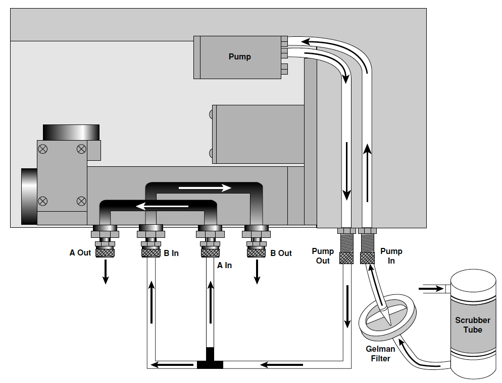
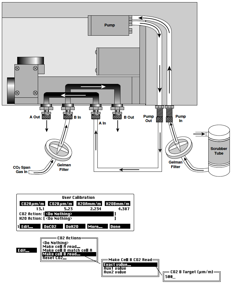
- Run a dry, CO2-free (zero) gas through cells A and B. The instrument could be plumbed as shown below, if you are using a soda lime/desiccant tube to generate the zero gas. You may want to review Section 6, Calibration, in the LI-7000 Instruction Manual if you are unfamiliar with the following calibration routines.
- Use the LI-7000 display, or the LI7000 PC software program to Make cell B match cell A.
-
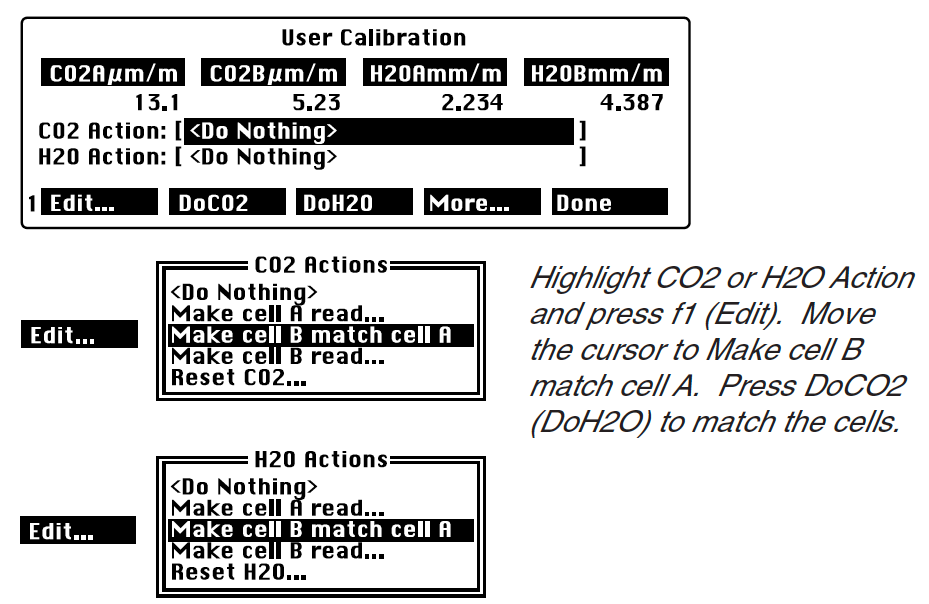
- If you have the means to create an H2O span gas (i.e., with the LI-610 Portable Dew Point Generator), re-plumb the instrument so that the zero gas flows through cell A, as shown below. Flow a span gas with known H2O concentration through cell B. Calibrate the H2O channel using the Make cell B read... option, and choose the target H2O concentration.
- Flow a span gas (if available) with known CO2 concentration through cell B. Calibrate the CO2 channel using the Make cell B read... option, and choose the target CO2 concentration.
-

- The preceding steps adjust the span parameter for the calibration polynomial. Any concentration in the B cell can be used to do this; there should, however, be a significant difference between the cell A and B concentrations. You might want to check some intermediate H2O and CO2 gases to verify the calibration.
-
Reload calibration coefficients and enter instrument serial number for use by USB port
- Start the LI-7000 Windows application and connect to the instrument using the RS-232 cable. The USB port cannot be used until the instrument serial number is entered below.
- Choose Cal Coefficients from the Configure menu. Click the Load From File button and load the coefficients from the file saved earlier in Step 1.
- Click the “Other” tab and enter the serial number of your instrument into the “Serial Number” field (i.e., IRG4-0123).
- Click OK.
- When prompted, press Yes to send the coefficients to the LI-7000.
The next time you attempt to connect to the LI-7000, the serial number entered above will appear in the Connect dialog under the USB tab, when the instrument is properly connected via the USB cable.