7200-101 Blower Motor Replacement
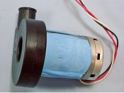
This installation guide describes how to replace the 7200-101 Flow Module blower motor (part number 9972-088). The procedure takes about 30 to 60 minutes. The tools required are:
| Hex keys: 1/16", 7/64", and 5/32" | Wrenches: 3/16" and 1/4" |
Disassembly
- Power off the flow module and disconnect the power cable.
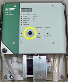
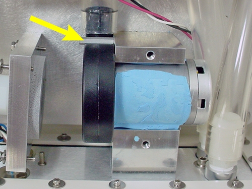
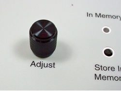
- Place the flow module on a level work surface. Remove the adjust knob using a 1/16" hex key.
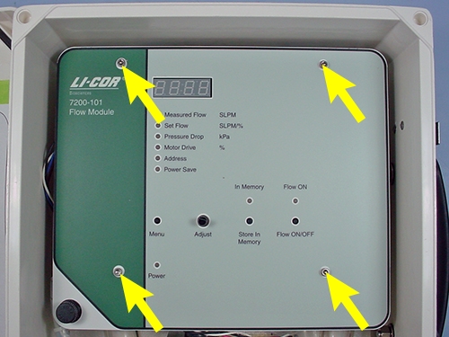
- Remove the four cap screws. Save the screws for re-use.
- Lift the panel straight up. Disconnect the power plug and set the panel aside.
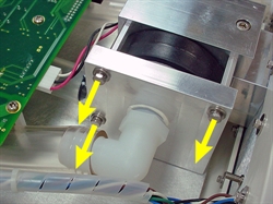
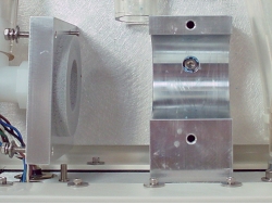
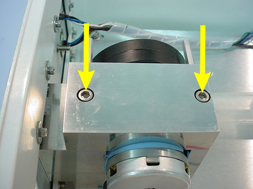
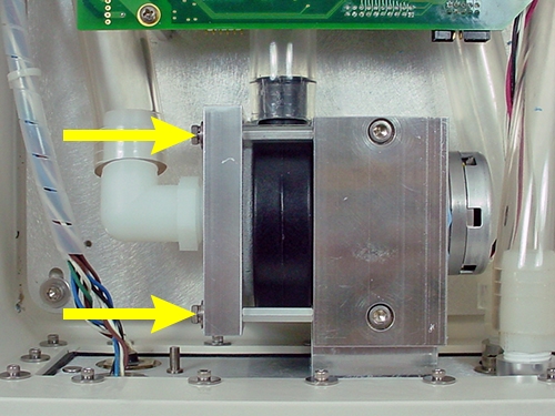
- Use the 1/4" wrench to remove the three screws that secure the blower plate. Separate the blower plate from the blower assembly. Save the screws for re-use.
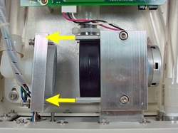
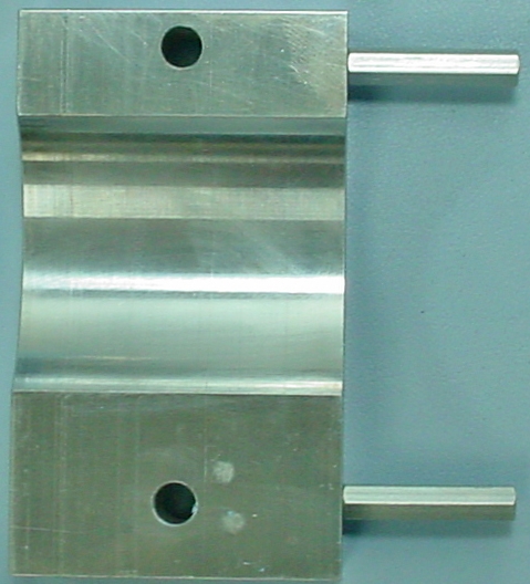
- Use a 5/32” hex key to remove the motor clamp. Use the 3/16” wrench to remove the remaining standoff. Save the cap screws and standoff for re-use.
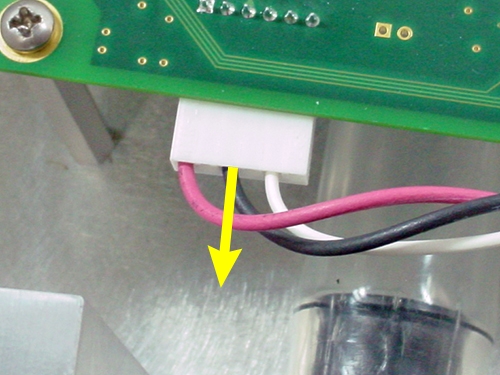
- Disconnect the cable and remove the blower motor assembly.
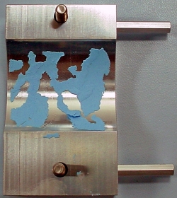
- Clean any residue from the thermal pad off of the motor mount and motor clamp.
Reassembly
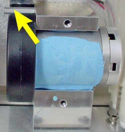
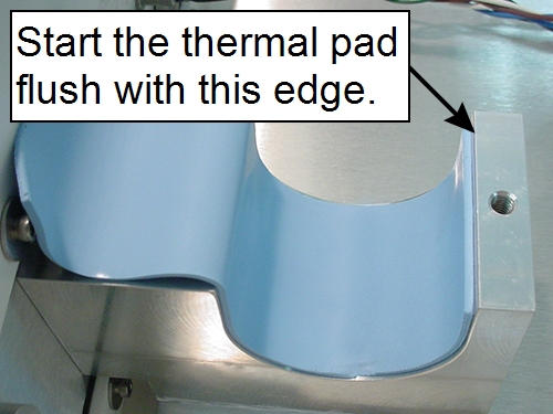
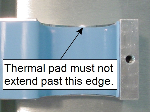
- Remove the backing material from both sides of the thermal pad and position it in the motor mount, as shown, keeping it away from the edge on the blower side of the motor mount.
- Press the outlet of the new blower assembly in to the existing 3.25” tubing.
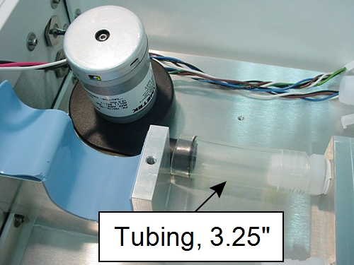
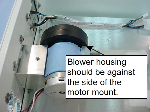
- Rotate the blower motor into position in the motor mount, making sure the blower housing is pressed against the side of the motor mount. Position the remaining part of the thermal pad over the top of the blower motor, as shown.
- Reinstall the bottom standoff using 3/16” wrench.
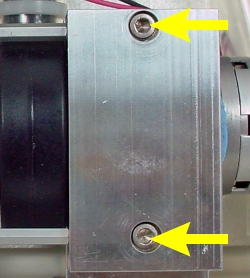
- Loosely install the motor clamp using the previously-removed cap screws.
- Make sure the blower housing, the motor mount, and the motor clamp are all flush. Alternate between cap screws as you tighten them. When done, there should be no gap between the motor clamp and the motor mount.
- Reinstall the blower intake plate assembly.
- Alternate between the hex cap screws and tighten the plate, compressing the gasket against the blower. When done, the plate should be tight against all three standoffs.
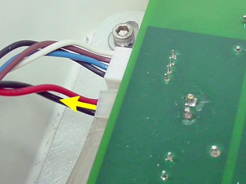
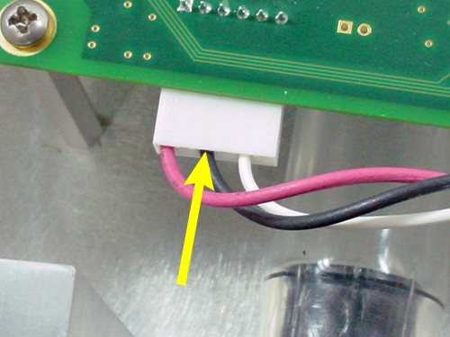
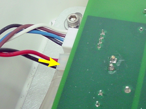
- Plug in the motor cable to connector P4. Plug the power cable from the panel in to connector P9.
- Carefully position the panel and install four cap screws (previously removed) to secure the panel.
-
- Depress the Menu, Store in Memory, and Flow ON/OFF buttons to verify that they work smoothly.
- Reinstall the adjust knob, leaving about 0.02 inches (5 mm) clearance between the knob and panel.
Blower replacement is complete.